


View more information
Watch a demo
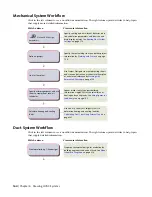
Place diffusers, VAV boxes, coils, dampers, and
other equipment by
on
page 194
-----
Connect the equipment using duct runs by
on page 196
-----
Verify flow values and calculate duct to properly
size components by
on page 203
-----
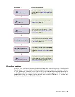
Modify system layouts based on design changes,
and recalculate sizes as necessary by
on page 219
-----
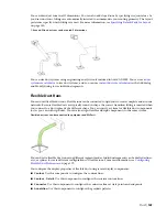
Make changes to a duct system
As you design, annotate systems for preliminary
design specifications and subsequent construction
-----
Label system components and
generate schedules
218
Associative movement lets you modify and move
duct and equipment to accommodate design
-----
changes without breaking connections. See
on page 219
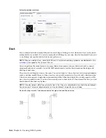
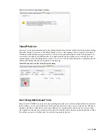
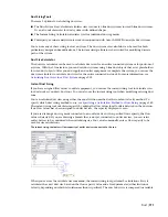
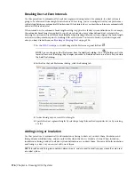
Flow Annotation
You can access flow annotation information for air terminals from the Flow Annotation tab in the Equipment
Properties dialog. You can specify up to 8 locations to place flow arrows around the air terminal. You can
select the block for the flow arrow, and you have the option of using the same block for all flow arrows or
selecting different blocks based on location. You can specify the rotation angle and the offset from the air
terminal for each flow arrow, and you can specify a flow value. The Flow Annotation tab is available only
after the air terminal has been added to the drawing.
Flow Annotation | 165
Summary of Contents for 235B1-05A761-1301 - AutoCAD MEP 2010
Page 1: ...AutoCAD MEP 2010 User s Guide March 2009 ...
Page 22: ...4 ...
Page 86: ...68 ...
Page 146: ...128 ...
Page 180: ...162 ...
Page 242: ...Modifying the elevation of a duct 224 Chapter 6 Drawing HVAC Systems ...
Page 264: ...246 ...
Page 480: ...462 ...
Page 534: ...516 ...
Page 616: ...598 ...
Page 658: ...640 ...
Page 788: ...770 ...
Page 802: ...784 ...
Page 820: ...802 ...
Page 878: ...860 ...


