3
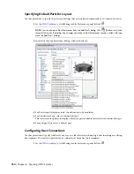
In the left pane, click HVAC
➤
HVAC Tags.
4
Click Text Tags.
5
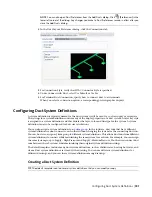
In the upper-right corner, click Next until you get to the page with the Space tag.
6
Move the cursor over the i-drop symbol.
7
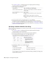
Drag the i-dropper from the Content Browser, and drop the space tag tool onto a tool palette.
8
To add the space schedule, repeat the previous steps. The Space Engineering Schedule is located
in HVAC
➤
HVAC Schedules of the Documentation Tool Catalog.
9
Close Content Browser.
For information on placing space tags on your drawing, see
on page 561. For information on scheduling
spaces, see
on page 566. You are more likely to use space tags and schedules in construct drawings
as design aids. You may not necessarily include them on view and sheet drawings for construction documents.
Creating a Duct System
After you
, you can create duct systems by adding equipment and duct runs to a
drawing. The most common way to add parts and duct runs is to use the tools on the HVAC tool palettes
set. Duct parts and equipment also contain grips you can use to draw duct runs directly from an object
without selecting a tool.
You can insert an architectural floor plan as a reference, and design duct systems around that floor plan.
After you create duct systems, you can modify them to refine your design, or to accommodate changes to
the building plan.
The topics in this section offer specific instructions on how to use the software features to create duct systems.
Adding HVAC Equipment
In the software, equipment is referred to as MvParts (multi-view parts), or simply parts. You can place parts
anywhere on a floor plan. You can add them as stand-alone objects, and then draw duct runs to connect
them, or you can add MvParts by connecting them to existing duct runs. MvParts have connectors that
allow them to connect directly with duct objects.
The software includes a default duct part catalog that contains hundreds of parts in thousands of sizes. The
part types range from large components, such as rooftop air conditioning units, to small components, such
as grilles.
If the part catalog does not contain the exact component you want to use, you can create your own custom
parts:
■
in AutoCAD or AutoCAD Architecture drawings to MvParts.
■
Use the Parametric Part Wizard
to quickly configure a parametric version of a common part.
■
to create all levels of block-based or parametric parts.
194 | Chapter 6 Drawing HVAC Systems
Summary of Contents for 235B1-05A761-1301 - AutoCAD MEP 2010
Page 1: ...AutoCAD MEP 2010 User s Guide March 2009 ...
Page 22: ...4 ...
Page 86: ...68 ...
Page 146: ...128 ...
Page 180: ...162 ...
Page 242: ...Modifying the elevation of a duct 224 Chapter 6 Drawing HVAC Systems ...
Page 264: ...246 ...
Page 480: ...462 ...
Page 534: ...516 ...
Page 616: ...598 ...
Page 658: ...640 ...
Page 788: ...770 ...
Page 802: ...784 ...
Page 820: ...802 ...
Page 878: ...860 ...

