Modifying Connectors
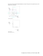
You can add, delete, and edit the connectors of a parametric part. The shape of the connector is determined
by the shape of the modifier that the connector is attached to. Therefore, to change a connector’s shape you
must modify the associated modifier. For more information, see
Adding Connectors to a Parametric Fitting
on page 682 and
Adding Connectors to a Parametric MvPart
on page 720.
Modifying Part Sizes
You can change the model dimensions of the part that determine the overall size of the model, such as
length and width. You can also change individual size parameters for a specific part size. For example, you
can change a constant value to a list of values or add custom parameters for enhancing scheduling data. For
more information, see
Adding Dimensions to a Parametric Fitting
on page 686 and
on page 724.
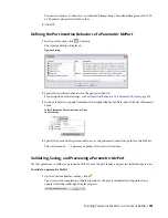
Modifying the Preview Image, Schematic Symbol, or Part Insertion Behaviors
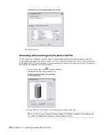
You can change the preview image by selecting a different view direction that Content Builder uses to
generate the preview image. You can also attach a predefined image. For more information, see
a Preview Image of a Parametric Fitting
Generating a Preview Image of a Parametric MvPart
on page 732.
You can change the insertion behaviors of the part that define how the part is added to a drawing, including
layer key, trim lengths for fittings, and the placement point of a parametric part. For more information, see
Defining the Part Insertion Behaviors of a Parametric Fitting
on page 690 and
Behaviors of a Parametric MvPart
on page 733.
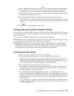
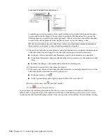
For parametric MvParts, you can also modify the schematic symbol. Schematic symbols can be predefined
symbol blocks or you can create them from scratch in the modeling area of Content Builder. Therefore, you
can attach a new schematic symbol or modify the schematic symbol block. For more information, see
Creating an AutoCAD-Based Symbol from an Existing Symbol or Block
on page 739.
Working with Block-Based Parts
A block-based part is a multi-view part (MvPart) whose geometry is based on individual AutoCAD
®
blocks.
Each part size is associated with a unique 3D model block, to which you specify basic information such as
view representations and connector placement. You can convert existing AutoCAD blocks or multi-view
blocks (MvBlocks) to block-based parts, and you can create block-based parts using Content Builder.
NOTE
For an introduction to block-based parts, see
Understanding Parametric and Block-Based Parts
on page 641.
Converting MvBlocks to Block-Based Parts
Use this procedure to convert AutoCAD
®
solids, mass elements, blocks, or multi-view blocks (MvBlocks)
into multi-view parts (MvParts). MvBlocks, like MvParts, can be viewed from different directions, but MvBlocks
cannot connect intelligently with systems.
Architectural drawings referenced in an AutoCAD MEP drawing can contain solids, mass elements, and
MvBlock parts that may be useful as MvParts. You can convert MvBlocks to MvParts even if the MvBlock
exists in a reference drawing.
This procedure is the same for mechanical, piping, electrical, and plumbing parts.
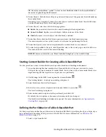
1
Select the element or block to convert, right-click, and select Convert to
➤
Multi-view Part.
2
In the Multi-view Part Convert - Behavior dialog, specify a name for the new part.
3
Specify a part type for Type.
Working with Block-Based Parts | 743
Summary of Contents for 235B1-05A761-1301 - AutoCAD MEP 2010
Page 1: ...AutoCAD MEP 2010 User s Guide March 2009 ...
Page 22: ...4 ...
Page 86: ...68 ...
Page 146: ...128 ...
Page 180: ...162 ...
Page 242: ...Modifying the elevation of a duct 224 Chapter 6 Drawing HVAC Systems ...
Page 264: ...246 ...
Page 480: ...462 ...
Page 534: ...516 ...
Page 616: ...598 ...
Page 658: ...640 ...
Page 788: ...770 ...
Page 802: ...784 ...
Page 820: ...802 ...
Page 878: ...860 ...

