


The calculation strings are displayed.
5
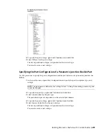
Double-click the value cell of PrtSN.
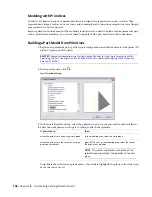
The Calculation Assistant dialog appears.
6
Define the part size name with a calculated value:
■
Highlight the value of PrtSN: Part Size Name and press
DELETE
.
■
Select 0 for Precision.
■
Under Insert Variable, select D1 and click Insert.
■
Click the value of PrtSN:Part Size Name and enter inch Dia.
■
Under Insert Variable, select PSTyp and click Insert.
■
Select PTyp and click Insert.
7
Click Evaluate. The calculation result is displayed. Click OK.
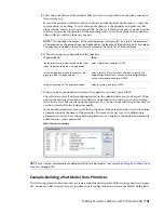
In the Size Parameters dialog, the calculation value of PrtSN is updated with the valid string
and, when selected, the result is displayed in the status bar.
IMPORTANT
The part size name is generated using VB (Visual Basic) Script’s FormatNumber function
and simple string substitutions. The correct syntax is crucial. Therefore, use the Calculator to ensure
that the string is valid.
Generating a Preview Image of a Parametric Fitting
Once you have finalized the part model, you generate a
on page 670 (BMP file) of the parametric
fitting. The preview image is helpful for identifying the part when users are selecting and adding parts to a
drawing. Content Builder generates the preview image based on a specified view direction. You can select
from the 10 standard AutoCAD
®
view directions to view the model (top, bottom, left, right, front, back, SW
isometric, SE isometric, NE isometric, and NW isometric).
1
To create a preview image, on the toolbar, click
.
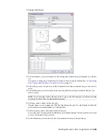
The Bitmap Preview dialog is displayed.
2
Under Generate View, click a view direction for the preview image of the part.
TIP
As you select a view, the preview image window in the dialog is updated. This enables you to
view all the available preview images for the part before selection.
You can also click Browse to navigate to and select a bitmap image. Predefined images must be
200 x 200 pixels saved with 256 colors.
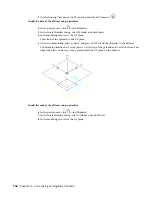
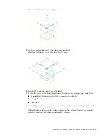
Defining the Part Insertion Behaviors of a Parametric Fitting
Once you have finalized the model and generated a preview image, you define the
page 671. These include the
trim lengths and placement point
on page 664 used by the software during
autolayout. Trim lengths define the distance that a connecting segment is trimmed in order for the fitting
to be placed in the run.
NOTE
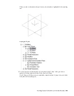
It is helpful to clean up the appearance of the model before defining trim lengths and the placement point.
To turn off all work planes and the associated geometry, profiles, and dimensions on those work planes, in the
part browser, right-click each feature and click Visible.
690 | Chapter 14 Customizing Catalog-Based Content
Summary of Contents for 235B1-05A761-1301 - AutoCAD MEP 2010
Page 1: ...AutoCAD MEP 2010 User s Guide March 2009 ...
Page 22: ...4 ...
Page 86: ...68 ...
Page 146: ...128 ...
Page 180: ...162 ...
Page 242: ...Modifying the elevation of a duct 224 Chapter 6 Drawing HVAC Systems ...
Page 264: ...246 ...
Page 480: ...462 ...
Page 534: ...516 ...
Page 616: ...598 ...
Page 658: ...640 ...
Page 788: ...770 ...
Page 802: ...784 ...
Page 820: ...802 ...
Page 878: ...860 ...


