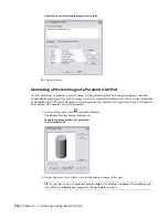
You can also browse to and select a predefined bitmap image. Predefined images must be 200
x 200 pixels and saved with 256 colors.
3
Click OK.
Defining the Part Insertion Behaviors of a Parametric MvPart
1
In the part browser, click
(Options).
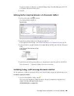
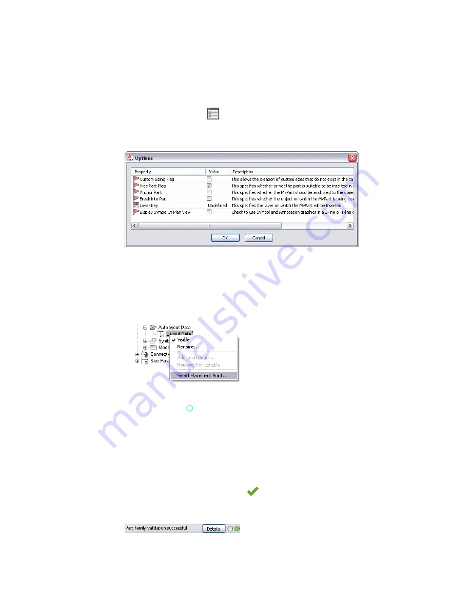
The Options dialog is displayed.
Options dialog
2
Specify the insertion behaviors for the part, and click OK.
For descriptions of the settings, see
Part Insertion Behaviors of a Parametric Part
on page 671.
3
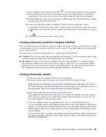
In the part browser, expand Autolayout Data, right-click Layout Data, and click Select Placement
Point.
Select Placement Point from Layout Data
context menu
4
Specify the point on the part model to use as the placement (insertion) point for the MvPart.
The software adds
(a placement point) at the selected location.
Validating, Saving, and Previewing a Parametric MvPart
Use this procedure to validate a parametric MvPart, save the part family, and preview individual part sizes.
To validate a parametric MvPart
1
On the Content Builder toolbar, click
.
Upon successful completion of these procedures, the part is validated and the status bar is
updated with the traffic light displayed green.
Building Parametric MvParts with Content Builder | 733
Summary of Contents for 235B1-05A761-1301 - AutoCAD MEP 2010
Page 1: ...AutoCAD MEP 2010 User s Guide March 2009 ...
Page 22: ...4 ...
Page 86: ...68 ...
Page 146: ...128 ...
Page 180: ...162 ...
Page 242: ...Modifying the elevation of a duct 224 Chapter 6 Drawing HVAC Systems ...
Page 264: ...246 ...
Page 480: ...462 ...
Page 534: ...516 ...
Page 616: ...598 ...
Page 658: ...640 ...
Page 788: ...770 ...
Page 802: ...784 ...
Page 820: ...802 ...
Page 878: ...860 ...

