


■
Click Manage tab
➤
Style & Display panel
➤
Style Manager drop-down
➤
Electrical System
Definitions
.
■
Click Manage tab
➤
Style & Display panel
➤
Style Manager drop-down
➤
Plumbing System
Definitions
.
■
Click Manage tab
➤
Style & Display panel
➤
Style Manager drop-down
➤
Schematic System
Definitions
.
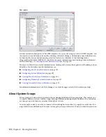
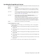
2
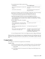
Purge the system definitions:
then…
If you want to…
right-click the system definition you want to re-
move, and click Purge.
purge one unused system definition
right-click System Definition, and click Purge. When
prompted, verify that the system definitions you
want to purge are selected, and click OK.
purge all unused system definitions
If the system definition you selected to purge remains in the list of system definitions after
purging, the system definition is currently applied to parts in the drawing.
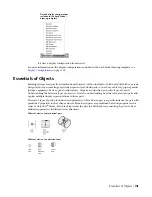
Selecting a Display Configuration
In addition to using orthographic and isometric views in a drawing, AutoCAD MEP includes many display
settings that control how objects appear in a drawing. Display representations control how objects appear
in different views. Display configurations are groups of display representations designed for specific tasks.
For example, you can change from a 1-line display configuration to a 2-line. You can also change to a
discipline-specific display configuration, such as one that shows mechanical systems in specified colors and
linetypes yet screens all other types of systems.
The default templates include display settings you can use for all aspects of project design and documentation.
You can also customize displays to meet specific project requirements. For more information on displays,
see
on page 135.
To change the current display configuration
1
Click the current display configuration in the
.
The displays included with the drawing are listed.
102 | Chapter 4 Drawing Essentials
Summary of Contents for 235B1-05A761-1301 - AutoCAD MEP 2010
Page 1: ...AutoCAD MEP 2010 User s Guide March 2009 ...
Page 22: ...4 ...
Page 86: ...68 ...
Page 146: ...128 ...
Page 180: ...162 ...
Page 242: ...Modifying the elevation of a duct 224 Chapter 6 Drawing HVAC Systems ...
Page 264: ...246 ...
Page 480: ...462 ...
Page 534: ...516 ...
Page 616: ...598 ...
Page 658: ...640 ...
Page 788: ...770 ...
Page 802: ...784 ...
Page 820: ...802 ...
Page 878: ...860 ...


