


As shown in the previous illustration, the default position of the Symbol and Annotation plane on the Z
axis in the World Coordinate System (WCS) is high above the WCS origin. This keeps the plane and its
contents out of the way while you are working on your part model. If desired, you can change the Z position
of the plane. To do so, right-click the plane in the part browser, click Change Plane Position, enter a new
value for the Z position, and press
ENTER
.
Creating Schematic Symbols for Parametric MvParts
You can create a schematic symbol for a parametric MvPart at any time. However, only parts that you add
to drawings after you have created the symbol can use the symbol. You cannot update previously inserted
parts to use the symbol.
There are 2 types of schematic symbols that you can add to parametric MvParts:
■
Parametric.
This type of symbol scales proportionally with the part. You create parametric symbols using
parametric features: parametric geometry, dimensions, and constraints.
■
Block-based.
This type of symbol scales uniformly instead of proportionally. You create block-based
symbols using standard AutoCAD objects, such as lines, arc, and circles. You can create the symbol from
scratch, or you can insert an existing AutoCAD MEP symbol or 2D AutoCAD block from a DWG file.
Creating a Schematic Symbol of a Parametric MvPart
on page 735.
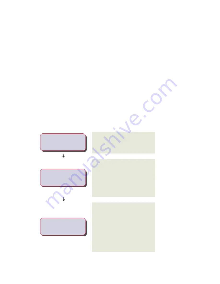
Workflow for Creating a Parametric Fitting with Content Builder
This workflow provides a road map for creating a parametric fitting using Content Builder.
View more information
Review the steps
You use the Content Builder in AutoCAD MEP to
create a parametric fitting. See
Parametric Building Environment
on page 676.
-----
Open the Parametric Building
Environment to start building
content.
You work in the parametric building environment
to create single parametric parts. In this
-----
Specify the part configuration.
environment, only one part can exist in a
drawing. The individual drawings are associated
with a part catalog to build a library of parts. You
specify the type and subtype of the part to
establish basic part behavior. See
Part Behavior of a Parametric Fitting
on page 676.
You create models of 3D parts and use them to
dynamically generate 2D views of your parts. You
-----
Create a 3D model of the part.
build your part from blocks, or features, that are
parametrically combined to define the part. The
model is defined in terms of the size, shape, and
position of its features. You can restrict how the
features of the parts fit together. To better
conceptualize the size and shape of the part
model, you define constraints and dimensions
that determine how your part is built. See
on page 677.
674 | Chapter 14 Customizing Catalog-Based Content
Summary of Contents for 235B1-05A761-1301 - AutoCAD MEP 2010
Page 1: ...AutoCAD MEP 2010 User s Guide March 2009 ...
Page 22: ...4 ...
Page 86: ...68 ...
Page 146: ...128 ...
Page 180: ...162 ...
Page 242: ...Modifying the elevation of a duct 224 Chapter 6 Drawing HVAC Systems ...
Page 264: ...246 ...
Page 480: ...462 ...
Page 534: ...516 ...
Page 616: ...598 ...
Page 658: ...640 ...
Page 788: ...770 ...
Page 802: ...784 ...
Page 820: ...802 ...
Page 878: ...860 ...


