


a device is assigned to multiple circuits on multiple panels, you must add a home run to each panel. This
allows you to subsequently tag each home run with the correct panel information. Make sure the locations
of the electrical connectors in the device style are not the same, so you are able to draw a home run from
each connector.
To draw a home run
1
Select an existing wire on the circuit, and click Wire tab
➤
General panel
➤
Add Selected
.
2
, select a device in the circuit.
3
Press
Enter
, and specify a point in the direction of the circuit’s panel.
Creating a Wire from a Polyline
You can convert an AutoCAD
®
line, arc, or polyline to a wire.
1
Select the line, arc, or polyline that you want to convert, right-click, and select Convert to
➤
Wire.
2
Do one of the following:
■
Press
Enter
or enter
n
(no) to leave the layout geometry in the drawing.
■
Enter
y
(yes) to erase the layout geometry from the drawing.
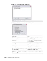
3
In the Modify Wires dialog, specify values for the wire properties, such as system and voltage.
4
Click OK.
Adding Electrical Equipment
After you add devices and panels to your layout and update the circuitry to include voltage and load
requirements, typically you continue by adding the electrical equipment needed to support the system. You
can place the equipment in specific locations on the floor plan.
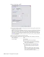
You add electrical equipment using the tools on the Equipment tool palette in the Electrical tool palette
group. You select a tool, use the Add Multi-view Parts dialog to select a part and configure its properties,
and then add the part to the drawing.
RELATED
Mechanical, Electrical, and Plumbing Equipment in Building Systems
on page 76.
To add electrical equipment
1
In the
, Click Home tab
➤
Build panel
➤
Equipment drop-down
➤
Generator
(or other provided equipment).
Adding Electrical Equipment | 419
Summary of Contents for 235B1-05A761-1301 - AutoCAD MEP 2010
Page 1: ...AutoCAD MEP 2010 User s Guide March 2009 ...
Page 22: ...4 ...
Page 86: ...68 ...
Page 146: ...128 ...
Page 180: ...162 ...
Page 242: ...Modifying the elevation of a duct 224 Chapter 6 Drawing HVAC Systems ...
Page 264: ...246 ...
Page 480: ...462 ...
Page 534: ...516 ...
Page 616: ...598 ...
Page 658: ...640 ...
Page 788: ...770 ...
Page 802: ...784 ...
Page 820: ...802 ...
Page 878: ...860 ...


