Amada MF-C2000A Series Operation Manual Download Page 95

3 . Changing the Equipment Settings

95

MF-C2000A Series

Chapter 2  V

arious Settings


Introduction Part

Inst
allat
ion and


Preparation Part

Operating Part

Maintenance Part

Appendixes

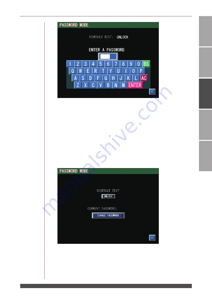
(3)  Enter the set password into the password input box.


Press the password by pressing keyboard keys on the screen.  The AC key de-

letes all the entered characters.  The BS key deletes a character in front of the 

cursor one by one.  The ENTER key is used to check the entered password for 

correctness.


At delivery, a password is not set. Press the ENTER key without inputting charac-
ters.  Then, set a password.


The password to be entered must consist of 4 alphanumerical characters.

(4)  Press the ENTER key on the keyboard.


When the entered password is correct, the new password setting screen is dis-

played.


When the entered password is wrong, the WRONG PASSWORD screen is dis-

played.


Then, enter the set password once again.

Summary of Contents for MF-C2000A Series

Page 1: ...AA04OM1209213 07 FIBER LASER WELDER MF C2000A Series OPERATION MANUAL ...

Page 2: ...the laser Experienced users can refer to the desired page from the table of contents Organization of This Document and Its Contents Introduction Part Explains the outline and functions of the laser Regarding the Fiber Laser this part explains the basic configuration and functional outline of this product including options so that the user can know the configuration of the laser and equipment compo...

Page 3: ...ion of Each Section on the Front Side 35 2 Name and Function of Each Section on the Top Side 36 Top Cover Section 36 Laser Controller MLE 122A 37 3 Name and Function of Each Section on the Lateral Side and Rear Side 38 Lateral Side and Rear Side Cover Section 38 Inside of the Connector Cover 39 Inside of the Connector Panel 2 Section MF C2000A MC SC Only 41 Installation and Preparation Part 43 Cha...

Page 4: ...1 Screen Configuration 79 Transition of Screens 79 2 Checking the Equipment Status 83 STATUS Screen 83 Setting the Output Status 84 TERMINAL MONITOR Screen 86 ERROR LOG Screen 87 EVENT LOG Screen 88 SOFTWARE VERSION Screen 89 3 Changing the Equipment Settings 90 CONFIG Screen 90 PASSWORD Screen 94 Protecting Set Values 94 INITIALIZE Screen 103 4 Setting the Laser Light Output Schedule MF C2000A M ...

Page 5: ...ng 167 Chapter5 LaserProcessingbyExternalCommunicationControl RS 485CONTROL 171 1 Operation Flow 171 2 Preparations for Operations 172 3 Initial Settings 173 Setting Communication Schedules and Equipment No 173 4 Commands 175 Setting Data 177 Reading Data 178 Setting the Control Method SCHEDULE No etc 187 Setting the System Date and Time 188 Reading the Control Method SCHEDULE No etc 189 Reading t...

Page 6: ...ng the Filter Cartridge 225 Replacing the Cooling Water 227 Inspecting Water Leaks from the Pump 227 Draining the Cooling Water 228 Cleaning the Dust proof Filter 229 4 Maintenance of the Dry Air Unit Option 230 Checking the Dry Air Unit 230 Checking the Filter Separator 231 Checking the Membrane Air Dryer 231 Chapter 2 Inspection and Measure To Be Taken at Occurrence of an Error 233 1 Error Displ...

Page 7: ...ition They are warnings about actions out of the scope of the warranty of the product Denote actions which operators must take Denotes that the content gives notice of DANGER WARNING or CAUTION to the operator Do not touch the inside of the Laser unnecessarily Since source voltage of 3 phase 200 V to 240 V AC is applied to the Laser high voltages are applied to its inside Do not touch the inside o...

Page 8: ...any cable The power cable and connecting cables may be broken and that can cause electric shock and fire If any part needs to be repaired consult us or your distributor Stop the operation if any trouble occurs Continuous operation after occurrence of a trouble such as burning smell abnormal sound abnormal heat smoke etc can cause electric shock and fire If such a trouble occurs immediately consult...

Page 9: ...ter cover it with non combustible material Do not apply the laser beam to combustible materials To avoid risk of fire never apply the laser beam to flammable or combustible materials Do not cover the Laser with a blanket cloth etc Do not cover the Laser with a blanket cloth etc while you are using it The cover may be overheated and burn Do not use this Laser for purposes other than metal processin...

Page 10: ...o contacts For details refer to E STOP Connector on page 160 Routine Handling Perform inspection periodically referring to the Maintenance Part Chapter 1 1 Maintenance Parts and Standard Intervals of Inspection Replacement on page 216 If the outside of the Laser is stained wipe it with a dry cloth or a moistened cloth If it is badly stained use neutral detergent or alcohol to clean it Do not use p...

Page 11: ...visor or operator enters the area where the laser is used protective measures not to exceed the MPE level must be taken MPE The maximum level of permissible exposure of the eyes or skin to laser beams Abbreviation of Maximum Permissible Exposure For other information on managing laser equipment or the MPE level refer to the following standards Japanese Industrial Standards JIS C 6802 Safety of Las...

Page 12: ... the Laser with its casters The casters are for fine adjustment Retract the level adjuster fully when transporting the Laser Precautions for using a pallet truck The following figure shows fork inserting positions As shown at right adjust the distance between the forks distance between the outer sides of the forks must be 400 to 520 mm but the fork must not hit the level adjuster When transporting...

Page 13: ...e enough clearance between the wall and the Laser For Packaging Precautions for packaging The worker must wear a helmet safety shoes and gloves for safety Leather gloves are recommended Retract the level adjuster fully when packing the Laser Take care that the Laser does not fall or slip Fix the skid to prevent slipping or install it on the non slipping surface For overseas transportation put the ...

Page 14: ...roof skids and make polypropylene bands approx 4 m x 4 go through grooves as shown below 3 Lift up the Laser with the pallet truck and place it on the vibrationproof skids Align the positions of FORK HERE and the forks and insert the forks vertically to lift up the Laser Height in moving upward 170 mm min Length 600 mm min Full width 400 to 520 mm Withstand load 300 kg min Polypropylene band ...

Page 15: ...of the Laser and then place the optical fiber on it Keep the minimum bending radius 200 mm or more and fix it with insulation locks three positions 6 Wrap the connector section of the optical fiber with an air cap to protect it Confirm that the water cooling connector is shorted Cushioning material Lock nut Level adjuster Optical fiber Air cap Caster Short circuiting tube ...

Page 16: ...for Handling 7 Cover the corrugated cardboard made top cap on the cushioning material at the top 8 Fix them with four polypropylene bands as shown below 9 Protect the Laser with an air cap or packaging wrap Polypropylene band Top cap ...

Page 17: ...ies For Disposal This product incorporates parts containing gallium arsenide GaAs At the time of disposal separate it from general industrial waste or domestic waste and carry out the disposal in accordance with applicable laws and regulations ...

Page 18: ...r Labels Sticking Warning Danger Labels Warning danger labels are struck on the laser Read the precautions provided on each label for correct use The numbers correspond to the label figure numbers on the next page 7 5 4 6 6 1 7 8 8 9 3 10 2 11 ...

Page 19: ...N 注意 ここを開きセーフティインタロックを解除すると クラス4のレーザ放射が出ます ビームや散乱光 の目 又は皮膚への被ばくを避けること CAUTION DEFEATED AVOID EYE OR SKIN EXPOSURE TO DIRECT OR SCATTERED RADIATION CLASS 4 LASER RADIATION WHEN OPEN AND INTERLOCKS 注意 装置のキャスターを使って運搬しないでください 装置の運搬には 許容荷重300kg以上のフォークリフト 又はハンドリフトなどを使用してください CAUTION DO NOT TRANSPORT THE LASER WITH ITS CASTERS WHEN TRANSPORTING THE LASER USE A LIFT TRUCK PALLET TRUCK ETC OF AT LEAST 300K...

Page 20: ...om Japan you need approval based on the said law For details please visit the Security Export Control s website or contact the Security Export Licensing Division Ministry of Economy Trade and Industry directly Security Export Control s website of Ministry of Economy Trade and Industry http www meti go jp policy anpo index html Security Export Licensing Division Ministry of Economy Trade and Indust...

Page 21: ...Introduction Part ...

Page 22: ......

Page 23: ...invisible to the human eye Most of laser equipment for laser welding belongs to class 4 laser that is the most hazardous in the classification of laser products speci fied in JIS When the laser light greets the eye it is focused by crystalline lens and reaches the retina thereby inviting a loss of eyesight Do not look at the laser light in any case Because both beams and scattered light are hazard...

Page 24: ...he manufacturing line for welding Single Delivery This is a sharing method of outputting a laser beam to a single optical fiber from the oscillator Timesharing This is a sharing method of outputting a laser beam from the selected optical fiber by operating the beamsplitter built in the laser equipment Up to 2 optical fibers can be connected with an oscillator for this laser equipment This is calle...

Page 25: ...sily and accurately performed MF C2000A MC SC only Language displayed on the Laser Controller can be switched between Japa nese and English A variety of input and output signals allow the Laser to be connected to auto matic machines Both the laser energy J and its mean power W are monitored If the desired energy range has been preset and the laser energy is out of the range the trouble signal is o...

Page 26: ...t work you can obtain data from the laser and change settings The laser supports EtherNet IP by using Anybus CompactCom 40 EtherNet IP of HMS Industrial Net works AB For detail specifications of EtherNet IP refer to the information issued by ODVA Inc Trademark EtherNet IP is a trademark of ODVA Inc Anybus is a registered trademark of HMS Industrial Network AB ...

Page 27: ...er Laser Welder MF C2000A Series 1 Package for accessories The model numbers of accessories are subject to change without notice De pending on the part to be changed the mounting screw shape may change and a necessary tool may be different For the latest parts information contact a near est sales office Product name Model No or specification Q ty Power cable 5 m AS1187143 1 Operation manual AS1209...

Page 28: ...S1204916 1 Scanner power cable 10 m 2 AS1209058 or AS1209059 3 1 LASER IF 2 short circuit connector 2 AS1209055 1 EXT I O 1 short circuit connector 2 AS1172045 1 1 Only for MF C2000A M S 2 Only for MF C2000A MC SC 3 Either one is attached depending on the specification of the scanner connected Main Unit Chiller and Output Unit or Scanner Head Unit This product is used in combination with the chill...

Page 29: ...livery φ0 05 mm 10 m N A 110 00 41 Single delivery φ0 05 mm 10 m Available 110 00 51 Single delivery φ0 05 mm 10 m Available 010 00 21 Single delivery beam coupler φ0 1 mm min Selected from table below N A 010 00 31 Single delivery beam coupler φ0 1 mm min Selected from table below N A 010 00 41 Single delivery beam coupler φ0 1 mm min Selected from table below Available 010 00 51 Single delivery ...

Page 30: ...at you selected at the time of purchase is connected to the main unit For details refer to the Operation Manual or Specifica tion for CL H201A or CL H601A Model Collimator lens f fθ lens f Active heat control For MF C2000A MC CL H201A 00 00 LP1206948 60 AS1206953 163 N A AS1206954 306 N A LP1206949 80 AS1206955 420 N A CL H601A 01 00 LP1206948 60 AS1206957 306 N A LP1206949 80 N A LP1206950 100 N ...

Page 31: ...ately sold Purchase them as required Part name Model No or specification Touch panel extension cable 5 m AS1162937 10 m AS1162938 15 m AS1162940 RS 232C RS 485 conversion adapter MSC 08S AC adapter for RS 232C RS 485 conversion adapter Exclusively for MSC 08 RS 485 cable 5 m AS1155931 10 m AS1156028 15 m AS1156029 RS 232C cable 0 2 m KRS 9F25F02K I O conversion harness for FL PL welder 1 AS1172103...

Page 32: ... 1 Memory 2 GB or more 16 GB or more when using the camera unit 1 Hard disk space 5 GB or more Display resolution 1024 x 768 dots or more 1366 x 768 dots or more when using the camera unit 1 Optical drive DVD ROM drive Interface Keyboard mouse LAN 10 100M LAN 1000M for connecting the camera 1 2 when using the camera unit 1 OS Windows 10 Pro 64 bit 3 1 The camera unit is an option for the scanner h...

Page 33: ...Fiber Laser Welder RS 232C RS 485 Conversion Adapter This conversion adapter is used to control equipment by external communication Output signals RS 232C of the personal computer are converted into RS 485 sig nals and then output to the main unit RS 485 cable Personal computer etc RS 485 connector of the main unit RS 232C RS 485 conversion adapter RS 232C cable ...

Page 34: ......

Page 35: ...e front side of the main unit Function of Each Section on the Front Side 1 Front Door This door is opened to perform maintenance including cable connec tions 2 MAIN POWER Switch Turns ON and OFF the power supply 3 Front Door Handle Used to open the front door Pull out the handle with the MAIN POWER switch OFF and turn it 90 degrees to the right to open the door After closing the door put back the ...

Page 36: ...and set values are displayed on the touch panel type liq uid crystal display 4 EMERGENCY STOP Button This is an emergency stop button With this button pressed the laser welder operation is stopped and the same state as that provided by turning OFF the CONTROL keyswitch is provided When the pressed button is turned in the direction of RESET clockwise the button is re set to the initial state 5 POWE...

Page 37: ...te from the laser welder Function of Each Section on the Laser Controller 1 Liquid Crystal Display Displays the setting conditions and monitor data 2 EMERGENCY STOP Button This is an emergency stop button With this button pressed the laser welder operation is stopped When the pressed button is turned in the direction of RESET clockwise the button is reset to the initial state This button functions...

Page 38: ...r oscillator are beyond the cover 2 FA Cooler For preventing the inside of housing from condensation 3 Connector Cover For the external I O connectors 4 Connector Panel 2 For MF C2000A MC SC various connectors are mounted 5 Optical Fiber Outlet The optical fiber is connected 6 Power Supply Terminals Connects the 3 phase power supply of 200 V to 240 V AC 10 and the grounding conductor Remove the co...

Page 39: ...om the drainage pipe when the Laser is used under high humidity environment Be sure to connect the attached drain hose to carry out drain piping Inside of the Connector Cover This section explains each section inside the connector cover Function of Each Section inside the Connector Cover 1 RS 232C 1 Connector Used for maintenance only Do not connect anything 2 RS 232C 4 Connector Used for maintena...

Page 40: ... this connector is closed the LD is turned OFF to shut off the laser light output 12 THMON Con nector BNC connector used to output an analog signal input to the TH connec tor between 0 to 5 V option 13 PWRMON Con nector BNC connector used to output an analog signal representing the monitor waveform of laser power When viewing the waveform of laser output connect to an oscilloscope The output range...

Page 41: ... cable The LAN standard is compatible with 100BASE TX 4 USER I O Con nector Connector for input and output with the external device PLC etc 5 LASER IF 2 Connector Short circuited with the dedicated cable When the scanner head unit is not used on MF C2000A MC SC con nect the dedicated short circuit connector 6 LASER IF 1 Connector The dedicated cable is connected Do not remove it 7 SCAN POWER Conne...

Page 42: ......

Page 43: ...Installation and Preparation Part ...

Page 44: ......

Page 45: ...ained below Install laser welder in a sure place at a level with the ground surface If the product is operated in inclined or fallen form a failure will occur Regarding the requirements of the power supply equipment refer to the table be low Input power supply Current capacity Main unit MF C2000A Series 3 phase 200 V 220 V 240 V AC 50 60 Hz 40 A or more Chiller specified one Single phase 200 V to ...

Page 46: ...equip ment a short circuit accident may occur to cause malfunction Therefore in laser processing be sure to install an exhaust device such as dust collector and blow er in a proper position to keep a clean environment Use the product in a place where the ambient temperature is 5 to 40ºC and the ambient humidity is 20 to 85 RH and yet a sudden temperature change does not occur If the humidity is hi...

Page 47: ...ill be frozen and the Laser may be broken Particularly in cold districts take care that the tempera ture of the Laser does not fall below 0 C When the product is not operated for 2 weeks or longer or the temperature is 0ºC or less bleed the equipment of cool ing water completely For bleeding refer to the Maintenance Part Chapter 1 3 Maintenance of the Chiller on page 228 When a sudden temperature ...

Page 48: ... The duty cycle is the ratio in percent of load time for the total time Laser output time Duty cycle Laser output time Laser pause time x 100 Example When the laser output set value is 1600 and the duty cycle is 60 output 1600 W of laser for 6 minutes and pause it for 4 minutes in for 10 minutes 40 C environment 200 400 600 800 1000 1200 1400 1600 1800 2000 0 20 40 60 80 100 Ambient temperature 40...

Page 49: ...aser Welder This section explains how to fix the laser welder on the floor Item required Phillips screwdriver adjuster pressure fixture and anchor etc Operating Procedure 1 Install the attached adjusters pressure fixtures on the adjusters provided in 4 po sitions in the lower part of the main unit Adjuster pressure fixture 4 positions Adjuster pressure fixture Adjuster 543 632 ...

Page 50: ...oor by using a connecting apparatus such as anchor The connecting apparatus is not attached as an accessory Prepare it on the customer side 74 5 59 94 19 5 50 19 33 48 20 14 Fixing hole to floor Lock nut Adjuster Adjuster pressure fixtures Fix on floor using anchor bolt Floor ...

Page 51: ...AUTION For the power supply side we earnestly recommend using a leakage breaker with the rated current of 40 A or more which is applicable to harmonics and surges Confirm that the Laser is grounded Item required Slotted screwdriver and Phillips screwdriver Operating Procedure 1 Open the terminal cover on the power supply terminals on the rear 2 Loosen the cable gland on the terminal cover to pass ...

Page 52: ...52 MF C2000A Series 1 Connecting the Power Supply 4 Install the terminal cover 5 Tighten the cable gland to secure the harness Power input terminals L1 L2 L3 PE White Black Green 8 sq Red ...

Page 53: ...ply side we earnestly recommend using a leakage breaker with the rated current of 20 A or more which is applicable to harmonics and surges Confirm that the Laser is grounded Item required Phillips screwdriver Operating Procedure 1 Connect the power cable attached to the chiller 2 Connect the alarm detecting cable connected to the chiller to the CH I L connec tor on the rear surface of the main uni...

Page 54: ...h end of the hoses to the water discharge port and the water outlet and inlet of the chiller Be careful about INLET and OUTLET 2 Connect the attached φ 8 tubes to the chiller connector and fix them with hose clips 3 Connect the φ 8 tubes connected to the chiller to the pipes of the fiber connector after being relayed by the φ 6 tubes with couplings It is recommended that the length of the φ 6 tube...

Page 55: ...in this position Rotate the nut 450 degrees clockwise with a spanner keeping the coupling body with another spanner from moving Reconnection method Before loosening the nut check its position This position is used as a reference later Remove the nut Check again that the front ferrule is mounted at the proper position Check that no foreign matter is attached to the body Insert the front ferrule unt...

Page 56: ...osion or clogging resulting in fault of the equipment When the chiller is operated for the first time after water feeding the water level lowers If it is lower than the lower limit replenish cooling water again Be sure to confirm that the feed water inlet filter is installed before supply the wa ter Otherwise the pump may fail due to contamination of foreign substances Remove the cap and confirm t...

Page 57: ...rainage is performed from the suction port on the heat radiation side Operating Procedure 1 Attach the drain hose to the drain port at the bottom of the FA cooler 2 Remove the front panel and install a cable tie Fix the drain hose surely with a cable tie CAUTION Install the drain hose as shown below When soaking the hose end in water When opening the hose end Cable tie Drain hose If there is no wa...

Page 58: ...recautions during Operation During operation wear fingerstalls or gloves During operation take care not to give shocks to the optical fiber or bend it below the minimum bending radius See table below Bending radius Min 150 mm Coil radius Min 200 mm Tensile force Max 50 N Torque torsion Max 0 5 Nm Torsion Max 90 per meter Do not tighten the connector section of output unit too firmly otherwise the ...

Page 59: ...e Part Appendixes 2 Remove the protective cap at the end of the optical fiber 3 Place the cleaning paper on the end of the quartz block 4 Place a drop of isopropanol in the quartz block area over the cleaning paper Wipe the quartz block by pulling the cleaning paper across it 5 Check that there is no stain dust and streak on the end of the quartz block and return the protective cap ...

Page 60: ... optical fiber is in line with the two red dots on the connector section Take care not to fall the O ring 2 Turn the connector section about 37 in the direction of the arrow 1 indicated on it Turn the connector section by hand without using a tool 3 Pull out the connector section about 2 mm and turn it in the direction of the arrow 2 ...

Page 61: ...d Preparations of Each Section Introduction Part Installation and Preparation Part Operating Part Maintenance Part Appendixes 4 Install the water cooling tube Be careful about IN and OUT For connection and cooling water refer to the Operation Manual for the output unit OUT IN ...

Page 62: ...ller from the main unit CAUTION Be sure to turn OFF the power supply before removing the laser controller Operating Procedure 1 Hold the handle located in front of the laser controller and lift it up with holding down its rear portion to remove it When putting the laser controller back in place wind the cable Be careful not to stuck the cable your fingers or hands in the housing Hold and lift up H...

Page 63: ...nal conversion adapter for external communication RS 232C RS 485 conversion adopter is required For making a connection to a PLC provided with RS 485 the conversion adapter for external communication is not required Item required RS 232C RS 485 conversion adapter RS 485 cable and RS 232C cable Operating Procedure 1 Connect the RS 485 cable to the RS 485 1 or RS 485 2 connector of the main unit 2 C...

Page 64: ...cedure 1 Confirm that the MAIN POWER switch is turned OFF 2 Open the connector cover on the rear to connect the cable for the heat detector to the TH connector 3 Turn OFF the CONTROL keyswitch and turn ON the MAIN POWER switch Power is supplied and the POWER lamp comes on 4 While the KEY SWITCH CHECK screen is displayed press the INITIALIZE but ton pressing the right button red portion in the figu...

Page 65: ... screen appears 5 Press the USER SETTING button The USER SETTING screen is displayed 6 To enable the active heat control function after connecting the cable for the heat detector press the ACTIVE HEAT CONTROL OPTION setting button and set it to USE When the active heat control function is not used set the button to NONE When USE is set with the cable disconnected error No 043 HEAT DETECTOR ERROR o...

Page 66: ...able to the SCAN POWER connector on the con nector panel 2 3 Connect the scanner control connecting cable to the SCANNER connector on the connector panel 2 4 Connect the scanner power cable to the power supply connector on the scanner head unit 5 Connect the scanner control connecting cable to the head I F connector XY2 100 on the scanner head unit CL H601A CL H201A Power supply connector Power su...

Page 67: ...eparations of Each Section Introduction Part Installation and Preparation Part Operating Part Maintenance Part Appendixes Computer Laser equipment Scanner head unit Optical fiber LAN cable Scanner control connecting cable Scanner power cable Camera connecting cable Option Camera unit ...

Page 68: ...versing the procedure When changing availability of the scanner head the output correction may be required For the output correction contact us Item required Phillips screwdriver EXT I O 1 short circuit connector and LASER IF 2 short circuit connector Operating Procedure 1 Turn OFF the MAIN POWER switch and open the connector cover on the rear 2 Disconnect the cable connected to the EXT I O 1 conn...

Page 69: ...ONTROL keyswitch and turn ON the MAIN POWER switch Power is supplied and the POWER lamp comes on 6 While the KEY SWITCH CHECK screen is displayed press the INITIALIZE but ton pressing the right button red portion in the figure below of the laser control ler Unless the CONTROL keyswitch is OFF the KEY SWITCH CHECK screen does not appear The INITIALIZE screen appears 7 Press the USER SETTING button ...

Page 70: ...the CL E MODE setting button and set it to OFF Note When the CL E mode is switched from ON to OFF all welding schedules are initial ized 9 Turn OFF ON the MAIN POWER switch again When the CL E mode is set to ON or OFF the model name on the startup screen changes ON OFF ...

Page 71: ...es the option setting and changes the chiller parameters The work performed by customers after the dry air unit is installed is as follows Item required Spanner 6 mm tube for dry air φ8 1 and recommended dry air 2 1 The destination coupling is MCLPTK8 1 MISUMI or equivalent 2 The recommended dry air is as follows The non recommended dry air may ad versely affect the filter effect and durability Te...

Page 72: ...s from 80 to 40 by the air flow rate Even for the equipment with the dry air unit condensation may occur on the cool ing part of the fiber connector or the cooling pipings on the outside of the equip ment To prevent condensation perform dehumidification of the installation envi ronment 0 10 20 30 40 50 20 30 40 50 60 70 Air flow rate ℓ min Time minute ...

Page 73: ...Operating Part ...

Page 74: ......

Page 75: ...unit is often called sequencer product name of Mitsubishi Electric Corporation Switching the Control Method Control by Laser Controller PANEL CONTROL When the laser is used independently or when the power supply of the PLC or per sonal computer connected to the laser is OFF the laser is under control by laser con troller To switch the control by external input output signals over to the control by...

Page 76: ... by sending a command to set the control method from the personal computer or the like connected to the main unit This control method cannot be selected by operating the laser controller or exter nal input output signals 2 Start and Stop This section explains the methods of starting and stopping the laser How to Start the Laser Operating Procedure 1 Turn ON the MAIN POWER switch The following scre...

Page 77: ...n to output laser light For the control by external input output signals execute the program by PLC switch the control method select output schedules set the sharing method and exert laser start stop to output laser light For the control by external communication control execute the program switch the control method set output schedules set the sharing method and exert laser start stop to output l...

Page 78: ......

Page 79: ... MONITOR STATUS and CONFIG screens to set a processing schedule There are 4 types of basic screen as shown below which are displayed on the liquid crystal display of the laser controller Each screen is selected to perform each setting by the button arranged on the right side of each screen Each time the screen selecting button is pressed each of the SCHEDULE screen MONITOR screen STATUS screen and...

Page 80: ...ed to change ON OFF setting Regarding the buttons with green lamp the selected screen button is displayed in green Regarding the ON and OFF buttons OFF lights out and ON lights up blinks When the OFF button is pressed a check window is displayed If OFF is switched over to ON by pressing the ON or YES button the ON setting lights up blinks Example When pressing ON blinking There are some buttons th...

Page 81: ...od When this button is pressed a window to select FIX fixed waveform FLEX flexible waveform of pulse oscillation or CW flexible waveform of CW contin uous oscillation is displayed Select a creating method by pressing an optional button The set method FIX FLEX or CW is displayed at the button LD Sets the LD to ON OFF When this button is pressed a window to select ON OFF is displayed At ON the LD co...

Page 82: ... MONITOR screen appears Select this button to check the measured value of laser light STATUS When this button is pressed the STATUS screen appears Select this button to check the laser equipment control method or check the op eration log and version CONFIG When this button is pressed the CONFIG screen appears Select this button to change various settings On the CONFIG screen SCHEDULE and FORM sett...

Page 83: ...ser controller RS 485 CONTROL external communication control Control is exerted by the personal computer connected to the RS 485 1 or RS 485 2 connector DELIVERY SYSTEM Displays the laser light sharing method SHOT COUNT GOOD COUNT Resets the displayed total number of laser light outputs SHOT COUNT Resets the displayed appropriate number of laser light outputs GOOD COUNT Pressing the RESET button r...

Page 84: ...US screen Control by Laser Controller PANEL CONTROL When the laser is independently used or when the power supply of the PLC or per sonal computer connected to the laser is OFF control is exerted from the laser con troller and PANEL CONTROL is displayed in CONTROL DEVICE Control by External Input Signal EXTERNAL CONTROL Connect the main unit to the PLC or the like and turn ON pin No 25 control swi...

Page 85: ...om the personal computer con nected to the main unit external communication control is selected and RS 485 CONTROL is displayed in CONTROL DEVICE on the STATUS screen Resetting the Number of Laser Light Outputs Reset the numeric values of SHOT COUNT total number of laser light outputs and GOOD COUNT appropriate number of laser light outputs that are displayed on the MONITOR screen 1 Press the RESE...

Page 86: ...EXT I O 1 EXT I O 2 How to see the displayed items Settable item INPUT Displays the current status of external inputs OUTPUT Displays the current status of external outputs EXT I O 1 Moves to the EXT I O 1 screen EXT I O 2 Moves to the EXT I O 2 screen SIM Sets the external output simulation mode to ON OFF This can be turned ON only at PANEL CONTROL X Returns to the STATUS screen When the SIM is O...

Page 87: ...s exceeds a thousand the histories beginning with the chronologically oldest history are overwritten How to see the displayed items Settable item Displays the date when the error occurred Displays the time when the error occurred E Displays the error code Displays the error messages corresponding to error codes Page Displays currently displayed page number total number of pages Scrolls the line up...

Page 88: ...ry are overwritten How to see the displayed items Settable item Displays the date when the event occurred Displays the time when the event occurred Input source Displays the input source of instruction which causes the event Event contents Displays the contents of equipment operation Page Displays currently displayed page number total number of pages Scrolls the line up and down When a line is not...

Page 89: ...ATUS screen the SOFTWARE VER SION screen appears On this screen the version of each software is displayed How to see the displayed items Settable item Unit name Displays the name of unit which uses the software PARTS NO Displays the parts number of software VERSION Displays the software version DATE Displays the updated date of software BUILD NO Numbers used for internal management at the time of ...

Page 90: ...TE and TIME Displays the setting screen for date and time ACTIVE HEAT CONTROL OPT Displayed when the active heat control function option is enabled When this button is pressed the setting screen for the upper limit value of temperature indication is displayed SET POWER SYNCHRONIZE Displayed when the set power synchronize function is enabled When this button is pressed the setting screen for the se...

Page 91: ...he BEAM are turned OFF when error No 035 LASER POWER OUT OF RANGE occurs and a laser stops LASER START DELAY Sets the acceptance time for laser start signal and schedule signal from 0 1 ms 1 ms 2 ms 4 ms 8 ms or 16 ms GUIDE BLINK Sets the guide light blinking status or continuous lighting to ON or OFF EXT IO PULSE WIDTH Sets the output time for end signal and monitor normal trouble signal from 20 ...

Page 92: ...n the range of 0 to 15 to perform remote operations by using the external communication function BAUD RATE Sets the communication speed from 9600 19200 38400 57600 or 115200 bps DATA BIT Sets the length of data bit from 8bit or 7bit PARITY Sets the parity mode from NONE EVEN or ODD STOP BIT Sets the stop bit from 2bit or 1bit X Returns to the CONFIG screen ...

Page 93: ...eparation Part Operating Part Maintenance Part Appendixes TCP IP COMMUNICATION SETUP How to see the displayed items Settable item ETHERNET ADDRESS Displays the Ethernet address IP ADDRESS Sets the IP address SUBNET MASK Sets the subnet mask DEFAULT GATEWAY Sets the default gateway address X Returns to the CONFIG screen ...

Page 94: ...LE EDIT Displays the protection status UNLOCK or LOCK At UNLOCK schedules can be changed At LOCK it is impossible to change schedules ENTER A PASSWORD When the input box is pressed the keyboard is displayed and a password can be entered X Returns to the CONFIG screen Protecting Set Values The method of protecting set values by setting the password is explained be low 1 Entering the Present Passwor...

Page 95: ... BS key deletes a character in front of the cursor one by one The ENTER key is used to check the entered password for correctness At delivery a password is not set Press the ENTER key without inputting charac ters Then set a password The password to be entered must consist of 4 alphanumerical characters 4 Press the ENTER key on the keyboard When the entered password is correct the new password set...

Page 96: ... a part of setting items is protected dis abling a change When UNLOCK is selected the display changes to UNLOCK and the protec tion is cancelled enabling a change 3 Setting a New Password 1 Press the CHANGE PASSWORD button The password change screen appears 2 Press the password input box upper portion The keyboard appears 3 Enter a new password into the password input box upper portion Enter 4 alp...

Page 97: ...RONG PASSWORD screen appears Press the OK button and enter the same password 6 Press the OK button The PASSWORD screen appears The display of CURRENT PASSWORD changes to the changed password The items that can be protected are as follows Display Screen Item SCHEDULE Screen SCHEDULE Schedule number FORM FIX FLEX CW waveform switching SET POWER Laser output set value RESOL Input resolution of output...

Page 98: ...ailed settings for the active heat control function MONITOR Screen SCHEDULE Schedule number FORM FIX FLEX CW waveform switching HIGH Upper limit value of laser energy to be monitored LOW Lower limit value of laser energy to be monitored STATUS Screen SCHEDULE Schedule number FORM FIX FLEX CW waveform switching SHOT COUNT Resetting the total number of laser light outputs SHOT COUNT GOOD COUNT Reset...

Page 99: ...ngs Introduction Part Installation and Preparation Part Operating Part Maintenance Part Appendixes SETTING AT DATE AND TIME How to see the displayed items Settable item DATE Sets year last two digits month and day TIME Sets time in a 24 hour period X Returns to the CONFIG screen ...

Page 100: ...ets the stage end signal width of the external output from 20 ms 30 ms or 40 ms SPAN Sets the scale of the measured temperature in the range of 0 500 to 2 000 for correcting the sensitivity of a sensor or the transmissivity when using the win dow material The initial value is 1 000 When 1 000 or less is set the upper limit of the measured temperature range becomes lower OFFSET Sets the deviation o...

Page 101: ...chronize can be set in No 1 to No 5 In an example of the screen above laser output set values of SCHEDULEs 0 and 10 are synchronized When the laser output set value of 0 is changed that of 10 is also changed into the same value The laser output set value cannot be changed if the setting error will occur in the synchronous schedule Also LINKED is displayed at the upper right portion of the SCHEDULE...

Page 102: ...factor An alarm is given when the state dew point x factor current humidity continues for the judgment time HUM READY coef Sets the proper humidity judgment time factor Factor alarm setting factor An alarm is canceled when the state of the proper humidity continues for the judgment time DRYAIR STOP coef Displayed when the dry air unit option is running Sets the dry air stop time factor The dry air...

Page 103: ...Part Appendixes INITIALIZE Screen On the INITIALIZE screen the settings can be initialized and the screen for setting such as the error output and the LD deterioration check is displayed How to see the displayed items Settable item INIT SCHEDULE Displays the confirmation window Press Yes to initialize the set values USER SETTING Displays the USER SETTING screen ...

Page 104: ...fault NONE Not output AUTO LD POWER CHECK Not used SET POWER SYNCHRONIZE Sets whether to use the set power synchronize setting Functions and displays related to the set power synchronize setting are valid only when this is set to USE NONE Not use default USE Use ACTIVE HEAT CONTROL OPTION Sets whether to use the optional heat detector setting Functions and displays related to the heat detector set...

Page 105: ...Turn OFF the CONTROL keyswitch and turn ON the MAIN POWER switch Power is supplied and the POWER lamp comes on 2 While the KEY SWITCH CHECK screen is displayed press the INITIALIZE but ton pressing the right button red portion in the figure below of the laser control ler Unless the CONTROL keyswitch is OFF the KEY SWITCH CHECK screen does not appear The INITIALIZE screen appears EMERGENCY STOP LAS...

Page 106: ... items Settable item SET POWER Sets the laser output Regarding FLASH1 to FLASH3 set the ratio sup posing that the set value is the reference value 100 Refer to REFERENCE VALUE for the forecast value of laser output Note The settable value of laser output is 200 to 2000 MIN The ratio of the preliminary oscillation output for SET POWER is displayed For the preliminary oscillation see page 108 SLOPE ...

Page 107: ...energy J based on the set laser output schedules is displayed Note There is a little difference between the forecast value of laser output energy and the measured value actually measured value depending on the optical and electrical characteristics Use the forecast value of laser output energy as refer ence RESOL When this button is pressed the selected setting resolution can be set from 0 01 ms o...

Page 108: ... POWER is selected There are limitations of the total time of the laser output time FLASH1 COOL1 FLASH2 COOL2 FLASH3 in combination with values of SET POWER and RE PEAT For details refer to Limitations of Schedule Setting on page 132 Within the range of 10 of the maximum SET POWER a constant power is output to protect the laser oscillator without reference to waveform input For details refer to Li...

Page 109: ...and laser output value at each point of POINT 01 to POINT 20 REFERENCE VALUE The forecast value of laser output energy J based on the set laser output schedules is displayed Note There is a little difference between the forecast value of laser output energy and the measured value actually measured value depending on the optical and electrical characteristics Use the forecast value of laser output ...

Page 110: ...laser stop signal is input Fn When this button is pressed a window to select function is displayed and the fol lowing editorial assistant functions can be used RESET Initializes the currently selected schedule COPY Copies the currently selected schedule to a temporary memory buffer PASTE Restores data from a temporary memory buffer to the currently select ed schedule For the common items in the up...

Page 111: ...value actually measured value depending on the optical and electri cal characteristics Use the forecast value of laser output as reference RESOL When this button is pressed the selected setting resolution can be set from 1 s 0 1 s 0 01 s or 0 001 s When the setting resolution is changed the currently selected schedule is cleared and the initial value is set MODU When this button is pressed the mod...

Page 112: ...e and output value of laser light in FLASH1 first laser to FLASH3 third laser by FIX Set the laser light that becomes a fixed waveform by up to 3 divisions In the following example SCHEDULE No 0 laser output value 1000 FLASH1 3 6 ms 100 COOL1 0 0 ms FLASH2 2 4 ms 85 COOL2 0 0 ms FLASH3 1 9 ms 50 up slope 0 6 ms and down slope 1 2 ms are set as output schedules 1 Press the SCHED button to display t...

Page 113: ...ut time so as to result in the fol lowing value FLASH1 COOL1 FLASH2 COOL2 FLASH3 500 0 ms 8 Press the SLOPE setting button Enter the time TIME ms required for laser light to up slope get gradually stronger in FLASH1 by using the numeric keypad and then press the ENT key Note The output time of FLASH1 includes the time of SLOPE Set SLOPE so as to result in the following value SLOPE FLASH1 9 Press t...

Page 114: ...CHEDULE screen 3 Setting ON OFF for the Output Schedules for Seam Processing 1 Press the SEAM button to display the SEAM screen 2 Press the SEAM setting button and set the seam processing output schedule to ON OFF At ON the fade function for seam processing set on the SEAM screen is en abled When this function is not used set OFF For the setting method of the output schedules for seam processing r...

Page 115: ...ntrol function set on the ACTIVE HEAT CONTROL screen is enabled For the setting method of the active heat control function refer to Setting the Active Heat Control Function Option on page 127 3 Press the X button to display the SCHEDULE screen 5 Checking Output Schedules 1 Check the waveform displayed on the screen The set laser output time and laser output value are graphically displayed and the ...

Page 116: ...d in REFERENCE VALUE In REFERENCE VALUE the forecast value of laser output energy based on the set output schedules is displayed This value is a little different from the actually measured value measured value displayed on the MONITOR screen provided at laser processing However use it as reference ...

Page 117: ... to 150 0 being the ratio to SET POWER set on the SCHEDULE screen SEAM Sets the fade function to ON or OFF Laser output value adjusting function The laser energy is increased de creased slowly to provide a continuous waveform suitable for seam pro cessing When this item is set to ON the fade function for seam processing is enabled When the item is set to OFF this function is disabled When this fun...

Page 118: ...ocessing against an excessive burn and makes the processing mark of the final shot inconspicuous The fade function can also be set for other processes than the beginning end of processing 1 Press the SEAM button to display the SEAM screen 2 Setting the Fade in out Function 1 Press the SHOT count setting button of POINT 01 Enter the laser light output count by using the numeric keypad and then pres...

Page 119: ...ple supposing that SHOT is set to 40 up to 40 shots are also validated for SHOT count Up to 40 of POINT 03 on the above screen When SHOT is set to 300 the POWER of the final set value is repeated up to 201 to 300 shots for SHOT count In this case the 20 energy of POINT 06 is repeated up to 201 to 300 shots 3 Enabling the Fade Function 1 Press the SEAM setting button to set it to ON The fade in out...

Page 120: ...the laser light modulation degree and the modulation frequency are set Rectangular wave RECT Triangular wave TRI Sinusoidal wave SINE How to see the displayed items Settable item DUTY Sets the duty ratio of the laser output value Sets the ratio of the High period for PEAK in a cycle in the range of 10 to 90 ...

Page 121: ...on becomes in the range between the minimum of the laser output and the maximum FREQUENCY Sets the frequency of the laser output value The setting range is 1 to 5000 Hz Sets the cycle of modulation MODU Set the modulation function to ON or OFF When this item is set to ON the settings is enabled When the item is set to OFF this function is disabled Note When using the modulation function set the la...

Page 122: ...of modulation wavelength is displayed as a graph on the MODU LATION screen Set the ratio of the period of High in a cycle in DUTY the modulation width in MODULATION and the repetition period frequency in FREQUENCY 2 Press the DUTY setting button Enter the ratio of the High period in a cycle by using the numeric keypad and then press the ENT key 3 Press the MODULATION setting button Enter the modul...

Page 123: ...ation width becomes up to 50 not exceeding 2000 W the maximum set output Ex 2 When performing modulation from the minimum to the maximum The modulation width whose center is 1000 W can be obtained by setting SET POWER to 2000 and POWER to 50 Set the modulation width to 100 At this time the minimum output is not 0 W but 100 W the preliminary oscillation The preliminary oscillation is a function for...

Page 124: ... the FREQUENCY setting button Enter the repetition frequency by using the numeric keypad and then press the ENT key 2 Enabling the Modulation Function 1 Press the MODU setting button to set it to ON When the modulation function is not used keep the MODU setting button OFF ...

Page 125: ... temperature reaches the target temperature KEEP Laser is turned on and off with the target temperature Switched each time the button is pressed Can be set for each schedule EXT OUT END When this button is selected the stage end signal Pin No 7 of the EXT I O 2 connector is output at the end of the stage This output time is specified in the STAGE END SIGNAL WIDTH on the HEAT DETEC TOR SETTING scre...

Page 126: ...nished at the time when the following operation is performed for the laser waveform with 500 ms Laser stops by the laser stop signal input within the time set in a schedule The next laser output starts The output setting or number of schedule is changed An error occurs KEEP POW Sets the output in KEEP operation in the range of 0 to 100 SMOOTHING Sets the moving average time of the measured tempera...

Page 127: ...thod of each stage of waveform According the number of stages of the set waveform the MODE setting buttons are displayed When the button of STAGE is pressed the STAGE dis play column is scrolled to the right and left so as to display a STAGE that is not yet displayed STAGE For the waveform set on the SCHEDULE screen a line representing the time is de fined as a stage STAGE 01 STAGE 02 and so on In...

Page 128: ...is lower than TARGET TEMP setting KEEP MODE setting Time Time KEEP POW TARGET TEMP Solid line Actual output waveform Broken line Set waveform Laser setting output waveform Detection temperature of the heat detector Detection temperature TARGET TEMP Output set for KEEP POW Detection temperature TARGET TEMP Output with the value set in the schedule SKIP SKIP MODE setting Time Time 0W Measuring lower...

Page 129: ...g value does not exceed the setting range 2 Making Detailed Settings 1 Press the EXPERT SETTING button to display the EXPERT SETTINGS screen 2 Accordingly set each items Setting the Correction Factor The indicated temperature is not a warranty value It may change depending on the workpiece material the surface condition or the angle of the output unit By changing the correction factor you can corr...

Page 130: ... dirty Note that the low temperature is also displayed in an environment where there is much dust or gas and humidity is high On the contrary when the high temperature is displayed check that there is no high temperature heat source or lighting nearby If there are no problems in particular adjust the correction factor to use it The temperature detection area differs depending on the lens configura...

Page 131: ... and paste functions you can transfer a schedule data to or from the buffer Also you can move a waveform data to another schedule appling these functions Operating Procedure 1 Select a schedule number to copy from 2 Press the Fn button and select COPY The schedule is copied into a memory buffer 3 Select a schedule number to copy to 4 Press the Fn button and select PASTE The data is restored from a...

Page 132: ...200 to 2000 W Total output time FIX sum of FLASH1 to 3 and COOL1 to 2 TIMEs FLEX CW sum of all TIMEs 0 1ms resolution 0 to 500 0 ms 0 05ms resolution 0 to 500 00 ms Can be set by a multiple of 0 05 ms 1s resolution 0 to 10000 sec 0 1s resolution 0 0 to 1000 0 sec 0 01s resolution 0 00 to 100 00 sec 0 001s resolution 0 000 to 10 000 sec REPEAT setting in pulse waveform Total output time sec 1 REPEA...

Page 133: ...displayed at certain intervals because the display timing is too quick AVERAGE Displays the average power W of output laser light In the FIX FLEX mode an upper lower limit judgment is not performed HIGH LOW Sets the upper limit value HIGH and lower limit value LOW of the laser energy to be monitored When the laser energy comes out of the set value range error No 035 LASER POWER OUT OF RANGE occurs...

Page 134: ...ys the peak temperature of the 1 SHOT waveform when the active heat control function option is enabled Note The indicated temperature is not a warranty value It may change depend ing on the workpiece material the surface condition or the angle of the output unit By changing the correction factor you can correct the indi cated temperature Refer to Setting the Correction Factor on page 129 Temperatu...

Page 135: ...ht and laser light waveform green line are displayed according to the set SCHEDULE When the active heat control function option is enabled the detected tempera ture waveform red line is displayed The detected temperature waveform is dis played for the time laser emission time MONITOR SPAN In the CW wave form however the display of the temperature waveform is finished at the time when the following...

Page 136: ...g the numeric keypad and then press the ENT key The upper limit value of allowable energy is registered 2 Press the LOW setting button Enter the lower limit value by using the numeric keypad and then press the ENT key The lower limit value of allowable energy is registered When laser light is out of the set allowable energy range error No 035 LASER POWER OUT OF RANGE occurs and a monitor trouble i...

Page 137: ...output SET POWER POWER set on the SCHEDULE screen The following formula is given to convert the set value into Watts POWER is also increased or decreased according to the output increase decrease between each POINTs When the measured value of the monitored laser light is out of the range shown by red lines below error No 035 LASER POWER OUT OF RANGE occurs Output Time Controlled waveform SET POWER...

Page 138: ... number is input The following timing chart shows the laser light output timing when the laser signal acceptance time is 16 ms and 4 ms 1 Laser start signal input 2 Laser light output Laser start signal input Laser light output acceptance 16 ms Laser light output acceptance 4 ms The laser start signal acceptance time and the schedule signal acceptance time are common A different value cannot be se...

Page 139: ... 2 Various Settings Introduction Part Installation and Preparation Part Operating Part Maintenance Part Appendixes 2 Changing the Acceptance Time 1 Set the LASER START DELAY 2 Press the X button The CONFIG screen reappears and the acceptance time for laser start signal and schedule signal is changed ...

Page 140: ...limited The touch panel also changes to the CL E mode display The content of limitation is as follows Common to Screens SCHEDULE No is fixed to 0 and FORM is fixed to CW CL E and EXT icons are also displayed CONFIG Screen ACTIVE HEAT CONTROL OPT and SET POWER SYNCHRONIZE setting but tons cannot be selected Also the functions cannot be selected with the CL E mode ...

Page 141: ...ITOR Screen The simplified MONITOR screen flexible waveform CW is displayed Press the TIME SCL button to set the estimated output time on CL E100A When the output exceeding the estimated output time error No 259 MONITOR POWER UNEXPECTED occurs The initial value of the estimated output time is 9999 s To display a more detailed monitored waveform set it lower ...

Page 142: ......

Page 143: ...Programmable Logic Controller EXTERNAL CONTROL and con trol by sending a command from the connected personal computer RS 485 CON TROL At PANEL CONTROL processing schedules are set by using the laser controller and laser light is output Operating Part MAIN POWER switch ON CONTROL keyswitch ON SCHEDULE Screen Setting and registration of SCHEDULE number output schedule number and output schedules Con...

Page 144: ... displays setting items setting buttons set values monitor data and windows and keyboard required for settings 2 EMERGENCY STOP Button This is an emergency stop button With this button pressed the laser equipment operation is stopped When the pressed button is turned in the direction of RESET clockwise the button is reset to the initial state This button functions in the same way as the EMERGENCY ...

Page 145: ...ut pin No 25 control switching of the EXT I O 1 connector to an open circuit to invalidate external input signals As a re sult the control by external input signals EXTERNAL CONTROL is invalidated and PANEL CONTROL is displayed in CONTROL DEVICE on the STATUS screen 1 Starting the Laser 1 Turn ON the MAIN POWER switch at the front of the main unit The power supply is turned ON and the POWER lamp c...

Page 146: ...the SCHEDULE setting button Enter the SCHEDULE number by using by using the and buttons or nu meric keypad and then press the ENT key In this example set 5 As the SCHEDULE number it is possible to set 255 schedules of 000 to 254 In FORM the fixed waveform FIX flexible waveform of pulse oscillation FLEX or flexible waveform of CW continuous oscillation CW can be speci fied When the registered SCHED...

Page 147: ...Note Set SLOPE so as to result in the following value SLOPE FLASH1 When setting FLASH2 or FLASH3 set the time required for laser light to down slow the laser output is gradually weaker to FLASH Set SLOPE so as to re sult in the following value SLOPE FLASH1 FLASH2 FLASH3 6 Press the POWER setting button of FLASH1 Enter the laser output value by using the numeric keypad and then press the ENT key In...

Page 148: ...ol switching of the EXT I O 1 connector remains in an open state external input signals are disabled and PANEL CONTROL is dis played in CONTROL DEVICE 2 Adjust the workpiece and output unit positions to set an appropriate work dis tance distance between the workpiece and the output position 3 Press the LD setting button The LD lights up 4 In the timesharing delivery press the BEAM setting button A...

Page 149: ...ht The GUIDE setting button is set to ON and a red dot of guide light appears at the laser light injecting position Laser light is injected to the red dot position 8 Check the laser light irradiation position If the point to be worked deviates from the red point of guide light adjust the po sition by moving the output unit or workpiece 9 Press the LASER START STOP button Laser light is output Befo...

Page 150: ... not turn OFF the MAIN POWER switch 1 Press the LD and GUIDE setting buttons on each screen to set them to OFF 2 Turn OFF the CONTROL keyswitch The key can be pulled out 3 Turn OFF the MAIN POWER switch The power supply is turned OFF and the POWER lamp goes out Return the key of the CONTROL keyswitch to the laser safety supervisor so that it can be kept in custody ...

Page 151: ...t the control by external input output signals EXTERNAL CONTROL output sched ules are set by another method PANEL CONTROL RS 485 CONTROL in advance After that such control as schedule selection laser light output and emergency stop is exerted PLC Programmable Logic Controller This unit exerts sequence control by executing the programmed contents of control in sequence This is often called Sequence...

Page 152: ...B CTH 10 HIROSE ELECTRIC CO LTD EXT I O 2 HDCB 37P 05 HDC CTH 10 REM I L 116 12A10 2AF10 5 TAJIMI ELECTRONICS CO LTD E STOP HDBB 25S 05 HDB CTH 10 HIROSE ELECTRIC CO LTD Prepare a program and its development environment for laser control on the cus tomer side It is recommended to use the shielded cable for inputting and outputting the con trol signal To exhibit the shield effect it is recommended ...

Page 153: ...of the attached connectors Plug Case Manufacturer HDBB 25P 05 HDB CTH 10 HIROSE ELECTRIC CO LTD Input Pins of EXT I O 1 Connector Close pin No 25 Pin No Description 1 24 V OUT Power supply for external input signals This pin is exclusively used for the MF C2000A Series Do not use it for any other purpose 2 LASER START When Pin 3 is closed the laser beam is output Make sure that the circuit is left...

Page 154: ...s OFF Note This pin can be used only when replacing our old products Use the E STOP connector for the emergency stop signal in accordance with machine safety standards 10 Input COM 19 0 V OUT Power supply for external input signals This pin is exclusively used for the MF C2000A Series Do not use it for any other purpose 24 Unused Do not connect anything 25 CONTROL CHANGEOVER While this pin is clos...

Page 155: ...t connect anything 20 Monitor trouble When the monitor value of laser energy is out of the range of HIGH and LOW set on the MONITOR screen the circuit is closed for 20 ms At the same time error No 035 LASER POWER OUT OF RANGE occurs 21 Output COM 22 End After the laser is output this pin is closed internally for 20 ms 23 External input receivable When an external input signal is acceptable when pi...

Page 156: ...e optical fiber selected to the branch 1 17 BEAM SELECT 2 Not used in the single delivery In the timesharing delivery when this pin is closed the branch 2 is selected and the unit becomes ready to project a laser beam from the optical fiber selected to the branch 2 18 Unused Do not connect anything 19 Unused Do not connect anything 20 Unused Do not connect anything 19 18 17 16 15 14 13 12 11 10 9 ...

Page 157: ...n terminal for input signals 36 Unused Do not connect anything 37 0V Ground for 24 V DC output Output Pins of EXT I O 2 Connector Pin No Description 1 24V OUT Power supply for external I O 2 Unused Do not connect anything 3 BEAM 1 ON Normally closed in the single delivery In the timesharing delivery while BEAM 1 is ON this pin is closed internally 4 BEAM 2 ON Not used in the single delivery In the...

Page 158: ...t anything 11 Unused Do not connect anything 12 AHC Stage end only when using the active heat control option When END of the relevant stage is selected this pin closed internally for the time specified in STAGE END SIGNAL WIDTH at the end of the stage This may be continuous with the next stage end signal 13 Unused Do not connect anything 14 Output COM ...

Page 159: ...F10 5 TAJIMI ELECTRONICS CO LTD Pin No Description 1 When the section between pin No 1 and pin No 2 is put an open circuit the LD is turned off 2 When the section between 2 pins of this connector is opened by operating the external interlock both guide light and laser output are stopped Connect this connector to the main interlock chamber interlock door interlock or other inter lock A multiple num...

Page 160: ...tween Pin No 14 and Pin No 19 between Pin No 3 and Pin No 5 and between Pin No 6 and Pin No 16 in closed circuits and then input the trouble reset signal 14 16 19 11 External interlock input 1 When the section between Pin No 11 and Pin No 24 is put in an open circuit the LD is turned off To cancel it put the section between Pin No 11 and Pin No 24 and the section between Pin No 12 and Pin No 25 in...

Page 161: ...iring can ren der the Laser unsafe CAUTION ALL CONNECTIONS ARE POTENTIAL FREE DRY CONTACT CLOSURE ONLY Do not apply any voltage or current or you will damage the system Do not connect to the power supply on the EXT I O 1 and 2 connectors Interlocks The interlocks cut off laser light in an emergency CAUTION The emergency stop and interlock are made up of two dry contact inputs These must be made to...

Page 162: ...s PLC and conveyor belt all of which have ES TOP buttons where one ESTOP button stops all devices Any situation in which more than one device must be connected together and respond identically to an emergen E STOP Connector ESTOP ESTOP ESTOP CH2 rtn ESTOP CH2 ESTOP CH1 ESTOP Out1a ESTOP Out1b ESTOP Out2a ESTOP Out2b Inside the laser User ESTOP Wiring 19 14 18 1 16 6 3 5 8 9 21 22 12 25 11 ESTOP CH...

Page 163: ...l emergency stop buttons In this example the Pilz device would also control additional emergency stop functions outside of the Laser using expan sion contacts The more devices which must be implemented the more expansion contacts must be added to the Safety Relay Module Any suitable IEC13849 1 com pliant safety relay controller is acceptable as long as it is implemented in this manner The end user...

Page 164: ...polarity may be positive or negative 1 1 Normally closed for Laser Stop Inside of the laser 10k 10k TLP180 TLP197G 24V EXT 0V 24V DC RY EXT I O 1 2 to 6 25 EXT I O 2 16 17 27 to 34 EXT I O 1 11 to 17 20 22 23 EXT I O 2 3 4 EXT I O 1 21 EXT I O 2 14 EXT I O 1 1 EXT I O 1 9 EXT I O 1 19 EXT I O 1 10 EXT I O 2 35 4 7k 4 7k TLP180 EXT 24V Input circuit Output circuit 24V DC Output COM Input COM Emerge...

Page 165: ...rt When Using a Contact Signal 10k 10k TLP180 TLP197G 24V EXT 0V RY EXT I O 1 2 to 6 25 EXT I O 2 16 17 27 to 34 EXT I O 1 11 to 17 20 22 23 EXT I O 2 3 4 EXT I O 1 21 EXT I O 2 14 EXT I O 1 1 EXT I O 1 9 EXT I O 1 19 EXT I O 1 10 EXT I O 2 35 4 7k 4 7k TLP180 EXT 24V 24V output 0V output 1 1 Normally closed for Laser Stop Load Inside of the laser Input circuit Output circuit Output COM Input COM ...

Page 166: ... 6 25 EXT I O 2 16 17 27 to 34 EXT I O 1 11 to 17 20 22 23 EXT I O 2 3 4 EXT I O 1 21 EXT I O 2 14 EXT I O 1 19 EXT I O 1 9 EXT I O 1 1 EXT I O 1 10 EXT I O 2 35 4 7k 4 7k TLP180 EXT 24V 24V output 0V output 1 1 Normally closed for Laser Stop Load Inside of the laser Input circuit Output circuit Output COM Input COM Emergency stop ...

Page 167: ...le is returned from the laser Press the STATUS button on the laser controller to display the STATUS screen Then you can confirm that EXTERNAL CONTROL is selected as the control method 2 Turning ON the LD Power Supply 1 Put pin No 4 of the EXT I O 1 connector in a closed circuit to turn ON the LD power supply Pin No 11 of the EXT I O 1 connector is put in a closed circuit after 5 seconds maximum an...

Page 168: ... connector in a closed circuit Laser light is output from the optical fiber Pin No 22 End output of the EXT I O 1 connector is put in a closed circuit for 20 ms and a signal is returned from the laser Pin No 17 Monitor normal out put or pin No 20 Monitor trouble output of the EXT I O 1 connector is put in a closed circuit for 20 ms and a signal is returned from the laser ON OFF ON OFF 1 sec max Ov...

Page 169: ...O 2 connector to an open circuit to turn OFF SCH 01 and put pin No 28 in a closed circuit to turn on SCH 02 7 Outputting Laser Light 1 Put pin No 2 Laser start of the EXT I O 1 connector in a closed circuit Laser light is output from the branch 1 The details are the same as Step 5 ON OFF ON OFF ON OFF ON OFF ON OFF ON OFF ON OFF ON OFF ON OFF ON OFF ON OFF ON OFF ON OFF ON OFF ON OFF ON OFF ON OFF...

Page 170: ... guide light before processing according to the following procedure 1 Adjust the workpiece and output unit positions to set an appropriate work dis tance distance between the workpiece and the output position 2 Put pin No 5 of the EXT I O 1 connector in a closed circuit Guide light can be seen as a red point Laser light is irradiated to this red point position 3 Check the laser light irradiation p...

Page 171: ...85 CONTROL At the control by external communication RS 485 CONTROL the original customer developed program is executed on the personal computer to set laser output sched ules and read monitor data and various types of status PLC Programmable Logic Controller This unit exerts sequence control by executing the pro grammed contents of control in sequence This is often called Sequencer product name of...

Page 172: ...n Part Chapter 1 Options on page 31 Prepare the program and its development environment for laser control on the customer side It is recommended to use the shielded cable To exhibit the shield effect connect the shield of a cable to FG frame ground inside the laser equipment Do not use it as SG signal ground A B C D E TxD TxD RxD RxD TxD TxD RxD RxD A B C D E TxD TxD RxD RxD TxD TxD RxD RxD RxD Tx...

Page 173: ... Transfer rate 9600 19200 38400 57600 115200 bps Data type Start bit 1 Data bit 8 or 7 Stop bit 2 or 1 Parity bit Even odd none Character code ASCII Set the transfer rate data type and equipment No by displaying the RS 485 COMMUNICATION SETUP from the CONFIG screen by the laser controller of each equipment that is connected to the personal computer etc Setting Communication Schedules and Equipment...

Page 174: ...ter the laser equipment No in the range of 0 to 15 by using the numeric key pad and then press the ENT key For controlling multiple lasers by single personal computer it is necessary to reg ister equipment No NETWORK for each equipment Set equipment No with out duplication If duplication of equipment No exists a data collision will occur on the communication line and the laser cannot be correctly ...

Page 175: ... T 0 E T X B C C Laser to PC S T X data E T X B C C Or C H 1 C H 0 N A K The schedule No or data No is out of the range WS Setting the control method SCHEDULE No etc PC to laser S T X C H 1 C H 0 W S S H 3 S H 2 S H 1 S H 0 c n t s 1 s 2 s 9 m o n E T X B C C Laser to PC C H 1 C H 0 A C K Or C H 1 C H 0 N A K The specified status cannot be provided or external communication control is not performe...

Page 176: ...ternal communication control is not performed C2 GOOD COUNT reset command PC to laser S T X C H 1 C H 0 C 2 E T X B C C Laser to PC C H 1 C H 0 A C K Or C H 1 C H 0 N A K External communication control is not performed RT Reading trouble PC to laser S T X C H 1 C H 0 R T E T X B C C Laser to PC S T X E 2 E 1 E 0 E 2 E 1 E 0 E 2 E 1 E 0 E T X B C C RH Reading the error history PC to laser S T X C H...

Page 177: ...e within the data range of 0000 to 0255 If spaces are entered the currently selected schedule is used DT1 DT0 Data No DT1 tens digit DT0 units digit For detailed information on the data No see Set Value Monitor Value Table on page 179 If 99 is entered data is written in a batch data Data No 1 Data No 2 Data No 3 the last Data No Insert between individual data The monitor data SHOT COUNT GOOD COUNT...

Page 178: ...veform data 095 to 099 SH3 SH2 SH1 SH0 Schedule No SH3 thousands digit SH2 hundreds digit SH1 tens digit SH0 units digit Enter the No of the schedule you want to read within the data range of 0000 to 0255 If spaces are entered the currently selected schedule is used DT1 DT0 Data No DT1 tens digit DT0 units digit For detailed information on the data No see Set Value Monitor Value Table on page 179 ...

Page 179: ...DULE screen Pulse repetition rate FIX FLEX 00001 01000 Cannot be set in the CW mode 05 SHOT on the SCHEDULE screen Number of consecutive shots FIX FLEX 0001 9999 Cannot be set in the CW mode 06 HIGH on the MONITOR screen Energy monitor upper limit setting FIX FLEX 000000 099999 0 1J 0 01J CW 000000 000999 1 07 LOW on the MONITOR screen Energy monitor lower limit setting FIX FLEX 000000 099999 0 1J...

Page 180: ...INT 04 TIME on the SCHEDULE screen 0000 5000 0 1ms 0000 9995 0 01ms 05 POINT 05 TIME on the SCHEDULE screen 0000 5000 0 1ms 0000 9995 0 01ms 06 POINT 06 TIME on the SCHEDULE screen 0000 5000 0 1ms 0000 9995 0 01ms 07 POINT 07 TIME on the SCHEDULE screen 0000 5000 0 1ms 0000 9995 0 01ms 08 POINT 08 TIME on the SCHEDULE screen 0000 5000 0 1ms 0000 9995 0 01ms 09 POINT 09 TIME on the SCHEDULE screen ...

Page 181: ...5 POINT 05 POWER on the SCHEDULE screen 0000 2000 0 1 06 POINT 06 POWER on the SCHEDULE screen 0000 2000 0 1 07 POINT 07 POWER on the SCHEDULE screen 0000 2000 0 1 08 POINT 08 POWER on the SCHEDULE screen 0000 2000 0 1 09 POINT 09 POWER on the SCHEDULE screen 0000 2000 0 1 10 POINT 10 POWER on the SCHEDULE screen 0000 2000 0 1 89 Schedule Settings for FLEX POWER 11 to 20 Data No Item Data Range 01...

Page 182: ...LE screen 0000 9999 1s 0 1s 0 01s 0 001s 05 POINT 15 TIME on the SCHEDULE screen 0000 9999 1s 0 1s 0 01s 0 001s 06 POINT 16 TIME on the SCHEDULE screen 0000 9999 1s 0 1s 0 01s 0 001s 07 POINT 17 TIME on the SCHEDULE screen 0000 9999 1s 0 1s 0 01s 0 001s 08 POINT 18 TIME on the SCHEDULE screen 0000 9999 1s 0 1s 0 01s 0 001s 09 POINT 19 TIME on the SCHEDULE screen 0000 9999 1s 0 1s 0 01s 0 001s 10 P...

Page 183: ...ion ON OFF 0 OFF 1 ON 0 1 76 SEAM setting value SHOT 01 to 10 Data No Item Data Range 01 POINT 01 SHOT on the SEAM screen 0000 9999 02 POINT 02 SHOT on the SEAM screen 0000 9999 03 POINT 03 SHOT on the SEAM screen 0000 9999 04 POINT 04 SHOT on the SEAM screen 0000 9999 05 POINT 05 SHOT on the SEAM screen 0000 9999 06 POINT 06 SHOT on the SEAM screen 0000 9999 07 POINT 07 SHOT on the SEAM screen 00...

Page 184: ... SEAM setting value POWER 11 to 20 Data No Item Data Range 01 POINT 11 POWER on the SEAM screen 0000 1500 0 1 02 POINT 12 POWER on the SEAM screen 0000 1500 0 1 03 POINT 13 POWER on the SEAM screen 0000 1500 0 1 04 POINT 14 POWER on the SEAM screen 0000 1500 0 1 05 POINT 15 POWER on the SEAM screen 0000 1500 0 1 06 POINT 16 POWER on the SEAM screen 0000 1500 0 1 07 POINT 17 POWER on the SEAM scree...

Page 185: ...nergy number of waveform data etc Data No Item Data Range 01 Schedule No of laser power monitor data 0000 0255 02 Unused Fixed to 000 03 ENERGY on the MONITOR screen Laser Energy 000000 999999 0 01J 04 Number of laser power monitor waveforms Total number of transmitted data with classification No between 01 and 20 Fixed to 100 05 Flash pulse width 0000 5000 0 1ms 01 Laser Power Monitor Waveform da...

Page 186: ... power monitor sent by R00 nn 04 to perform repeated reading 51 LD Output Total Time Data No Item Data Range 01 FLASH WORK TIME on the STATUS screen 0000000 9999999 0 1H 40 Backup Memory Settings Data No Item Data Range 01 NETWORK on the CONFIG screen 00 15 02 IP ADDRESS on the CONFIG screen 000000000000 999999999999 03 SUBNET MASK on the CONFIG screen 000000000000 999999999999 04 DEFAULT GATEWAY ...

Page 187: ...y customer In the maintenance mode the control method cannot be changed When the CONTROL keyswitch is turned OFF the control method is re turned to 0 Control by laser controller when the control by external input output signals is OFF To change the control method blank all the other items When the control by external input output signals EXTERNAL CONTROL is ON The control by external input output ...

Page 188: ...c laser power monitor value transmission 0 OFF 1 ON Current status kept Each time the laser is output 00 Laser Power Monitor Energy number of waveform data etc on page 185 is sent In the case of a high speed repeat ed output however the data is sent at certain intervals because the commu nication is too quick Even if the control method is changed in cnt the data is sent automatically until the pow...

Page 189: ...s digit cnt Control method 0 Control by laser controller 1 Control by external input output signals Output schedules are set on the laser controller 2 Control by external communication control 3 Maintenance mode 4 Missing number 5 Control by external input output signals Output schedules are set on the personal computer s1 LD 0 OFF 1 ON s2 Guide light 0 OFF 1 ON s3 Unused fixed to 0 s4 Single deli...

Page 190: ...If not the Laser returns a NAK The Laser is not ready for use when An alarm is activated LD is OFF The Laser is not in external communication control mode Personal computer etc Laser Personal computer etc Laser S T X E T X B C C S T X C H 1 C H 0 R D E T X B C C Personal computer etc Laser 1 2 3 Personal computer etc Laser Personal computer etc Laser 4 5 A C K N A K W D Y 3 Y 2 Y 1 Y 0 M O 1 Or M ...

Page 191: ... C K N A K Or C H 1 C H 0 C H 1 C H 0 A C K N A K Or C H 1 C H 0 C H 1 C H 0 A C K N A K Or C H 1 C H 0 C H 1 C H 0 S T X C H 1 C H 0 E T X B C C 0 S T X C H 1 C H 0 E T X B C C 9 C S T X C H 1 C H 0 E T X B C C 0 C S T X C H 1 C H 0 E T X B C C 1 7 8 9 10 Laser Personal computer etc Laser Personal computer etc Laser Personal computer etc Laser Personal computer etc Laser A C K N A K Or C H 1 C H ...

Page 192: ... has occurred the error No is to be 000 For the contents corresponding to error No refer to the Maintenance Part Chapter 2 1 Error Display and How to Take a Measure on page 233 11 12 Personal computer etc Laser Personal computer etc Laser C S T X C H 1 C H 0 E T X B C C 2 R S T X C H 1 C H 0 E T X B C C T A C K N A K Or C H 1 C H 0 C H 1 C H 0 S T X E T X B C C E 2 E 1 E 0 E 2 E 1 E 0 E 2 E 1 E 0 ...

Page 193: ...s digit CP0 units digit 00 CPU 01 MAIN FPGA 02 SUB FPGA If 99 is entered data is read in a batch Laser S T X E T X B C C S T X C H 1 C H 0 R D E T X B C C Personal computer etc Laser 2 3 Personal computer etc Laser Personal computer etc Laser 4 5 Y 3 Y 2 Y 1 Y 0 M O 1 M O 0 H 1 H 0 M I 1 M I 0 R H R V R N I D 3 I D 2 I D 1 I D 0 C P 1 C P 0 name version error D 1 D 0 S T X C H 1 C H 0 S T X C H 1 ...

Page 194: ...etween individual data Reading the Equipment Name The command code RN to read the equipment name is explained below CH1 CH0 Equipment No CH1 tens digit CH0 units digit name Equipment name Personal computer etc Laser 3 Personal computer etc Laser Personal computer etc Laser 4 5 R H R V R N I D 3 I D 2 I D 1 I D 0 C P 1 C P 0 name version error S T X C H 1 C H 0 S T X C H 1 C H 0 S T X C H 1 C H 0 E...

Page 195: ...or At the control by external input output signals output schedules are set by SWDraw3 in advance After that such control as schedule selection laser light output and emergency stop is exerted PLC Programmable Logic Controller This unit exerts sequence control by executing the programmed contents of control in sequence This is often called Sequencer product name of Mitsubishi Electric Corporation ...

Page 196: ... turned OFF 2 Confirm that the laser welder and computer are connected with the LAN cable 3 Turn ON the MAIN POWER switch at the front of the main unit The power supply is turned ON and the POWER lamp comes on The memory and power supply unit are automatically checked When no error is found the KEY SWITCH CHECK screen is displayed 4 Turn ON the CONTROL keyswitch The engine oscillator is automatica...

Page 197: ...E SCL button to set the estimated output time on CL E100A Select a time longer than the scanning time 2 Starting the Computer 1 Double click the SWDraw3 icon on the desktop to start the SWDraw3 applica tion After SWDraw3 starts the Drawing screen is displayed 2 Confirm that the equipment is connected correctly by checking the status display field on the Drawing screen Online displayed in the title...

Page 198: ...WDraw3 5 Stopping Laser Processing CAUTION During a laser light output or for 5 seconds immediately after a laser light output do not turn OFF the MAIN POWER switch 1 From the menu select Laser Control Control The Control screen appears 2 When the LD is ON click the LD OFF button 3 The Cooling down message is displayed on the Drawing screen while operation is stopped ...

Page 199: ...t shut off the power while Online is displayed in the title bar Shutting off the power switch while Online is displayed may result in the loss of data on memory card preventing the system from restarting 4 The Cooling down message disappears on the Drawing screen after the LD has finished shutting down 5 Click the Offline button on the Control screen 6 Click the Close button to close the Control s...

Page 200: ... OFF the CONTROL keyswitch The key can be pulled out 10 Turn OFF the MAIN POWER switch The power supply is turned OFF and the POWER lamp goes out Return the key of the CONTROL keyswitch to the laser safety supervisor so that it can be kept in custody ...

Page 201: ...IVE HEAT CONTROL and POWER CORRECT ASSIST functions Connect the PLC to the USER I O connector provided at the connector panel 2 to control the main unit by executing the program from the outside As another system for safety a remote interlock must be connected as a matter of duty The E STOP connector the REM I L connector when replacing our old prod ucts is connected to the interlock of the door o...

Page 202: ... point 2 BK short point 2 RD short point 2 BK short point 2 RD short point 2 BK short point 2 RD short point 2 BK short point 2 RD short point 3 BK short point 3 RD short point 3 BK short point 3 RD short point 3 BK short point 3 RD short point 3 BK short point 3 RD short point 3 BK short point 3 RD short point 4 BK short point 4 RD short point 4 BK short point 4 18 52 19 53 20 54 21 55 22 56 23 5...

Page 203: ...art Maintenance Part Appendixes Installation and Preparation Part Terminal treatment Cables are aligned at the laminated part in order When performing wiring peel them from the laminate tape Also avoid the use of the part peeled from the lami nate tape 30 mm since the cable coating may be deformed In addition the lami nated part cannot be used for pressure contact ...

Page 204: ...0 49 48 47 46 45 44 43 42 41 40 39 38 37 36 35 0V OUT 0V OUT Layout no confirmation out Data error out Strobe out Bootable out External input receivable out Remode out Warning out Trouble out Ready out Guide beam ON out LD ON out Laser output out 0V OUT 0V OUT 24V OUT 24V OUT Output COM in Layout no confirmation strobe in Layout no selection binary code 512 in Layout no selection binary code 256 i...

Page 205: ... falling edge of opening 8 Error reset Trouble reset Close input cancels the trouble output 9 Unused Do not connect anything 10 Unused Do not connect anything 11 Unused Do not connect anything 12 Control switching While this pin is closed the remote mode is set and the external input signals are effec tive 13 Operation complete input ACK The carriage control operation is checked to resume the scan...

Page 206: ...it for any other purpose 33 24 V OUT Power supply for external I O Do not use it for any other purpose 34 24 V OUT Power supply for external I O Do not use it for any other purpose 35 0 V OUT GND for external I O Do not use it for any other purpose 36 0 V OUT GND for external I O Do not use it for any other purpose 38 Laser output for indicator While the laser is output this pin is closed internal...

Page 207: ...rnal input signal is not acceptable if it is input 49 Bootable While the LD is supplied this Pin 49 COM circuit is closed internally 50 Strobe Turned ON when the carriage control operation is permitted 51 Reserve Do not connect anything 52 Reserve Do not connect anything 53 Data error When an unregistered layout no is selected this Pin 53 COM circuit is closed internally until it is reset 54 Reser...

Page 208: ...208 MF C2000A Series 4 Connector Functions REM I L Connector E STOP Connector Refer to the Operating Part Chapter 4 ...

Page 209: ...ls An example of external input output signal connections is explained below When Connected to an External Power Source Inside of the laser 10k 10k TLP292 4 TLP172GM Load 24V DC 2 USER I O 1 2 33 34 USER I O 38 to 43 47 to 53 56 2 The polarity may be positive or negative 1 1 Normally closed for Laser Stop USER I O 32 66 USER I O 4 to 8 12 13 16 to 26 USER I O 35 36 67 68 USER I O 3 37 EXT 24V Inpu...

Page 210: ...he laser 10k 10k TLP292 4 TLP172GM Load USER I O 1 2 33 34 USER I O 38 to 43 47 to 53 56 1 1 Normally closed for Laser Stop USER I O 32 66 USER I O 4 to 8 12 13 16 to 26 USER I O 35 36 67 68 USER I O 3 37 EXT 24V Input circuit Output circuit Output COM Input COM 24V output 0V output ...

Page 211: ...ixes Installation and Preparation Part When Using an Open Collector Signal Inside of the laser 10k 10k TLP292 4 TLP172GM USER I O 1 2 33 34 USER I O 38 to 43 47 to 53 56 Normally closed for Laser Stop USER I O 32 66 USER I O 4 to 8 12 13 16 to 26 USER I O 35 36 67 68 USER I O 3 37 EXT 24V Input circuit Output circuit Load Output COM Input COM 24V output 0V output ...

Page 212: ......

Page 213: ...Maintenance Part ...

Page 214: ......

Page 215: ...g items and take extreme care WARNING Before starting maintenance operations be sure to turn OFF the power supply Turning ON the power supply for an operation check during maintenance puts the laser in oscillation Take extreme care about it The operator and those who may receive laser light during maintenance must put on protective glasses CAUTION Use our genuine maintenance parts For defect cause...

Page 216: ...SVB SW 5 years Replace Switching power supply PLA300F 12 5 years Repair or Replace PLA300F 24 FETA7000T 144 Relay G7Z 3A1B 11Z R DC24V 5 years Replace Electromagnetic contactor SC 03 G 5 years Replace Rear fan AS1209225 5 years Replace Optical unit 4 MF C2000A M MC FLC 2000M W CF 0513 AMY 4 years Replace MF C2000A S SC FLC 2000S W CF 0310 AMY Mechanical seal kit for chiller HRG S0211 3 years Repla...

Page 217: ...about one month the usable period of the lithium battery is shortened 4 The optical unit is the laser oscillator including the excitation LD If the la ser output drops down and the processing conditions cannot be restored despite setting the maximum output it is determined as the end of its use ful life The warranty is valid for a period of two years However usage out of specifications for example...

Page 218: ...g Procedure 1 Turn on the guide light and adjust the posi tion so that the beam diameter becomes about 2 3 of the diameter at the light receiv ing part 2 Output the laser light and measure it If the output is low clean or replace the protec tive glass of the output unit For replacement refer to the operation manual for the output in use Also check whether there is no change in mea surement environ...

Page 219: ...n if SET POWER on the SCHEDULE screen is set to the maximum value 1 Validating the Laser Power Correction Function 1 Turn OFF the CONTROL keyswitch and turn ON the MAIN POWER switch Power is supplied and the POWER lamp comes on 2 While the KEY SWITCH CHECK screen is displayed press the INITIALIZE but ton pressing the right button red portion in the figure below of the laser control ler Unless the ...

Page 220: ...setting button Enter the laser output set value by using the numeric keypad and then press the ENT key Note Set the laser output value around the rated output after measuring with a low val ue Refer to Inspecting the Laser Output on page 218 4 Press the laser output time TIME sec and laser output value POWER setting buttons of POINT 01 to POINT 05 Enter each value by using the numeric keypad and t...

Page 221: ...about 1 second 2 Set up the power meter Operate according to the display of the yellow line Confirm that the power meter is placed at the proper position After wearing protective glasses and confirming that the safety against the scattered light is ensured press the button 3 Press the UP button to increase the output and the DOWN button to decrease it Adjust it within the range of gauge One clicki...

Page 222: ...e UP DOWN adjustment again Since the adjustment range 100 to 110 is displayed by an integer the displayed numeral value may not change even if the buttons are pressed but it actually changes by approx 0 5 to 2 CAUTION The laser power correction function is for restoring the lowered output Make sure not to exceed the rated output It will not coverd by the warranty even if it is still within the war...

Page 223: ...to Perform Maintenance Introduction Part Operating Part Maintenance Part Appendixes Installation and Preparation Part 6 Press the LD setting button to set it to OFF and press the END button When a further adjustment is necessary repeat Step 3 EMERGENCY STOP LASER START STOP ...

Page 224: ...ive glass every day and replace it every month For how to clean and replace the protective glass refer to the operation manual for the output unit in use CAUTION Using a dirty protective glass may make the laser beam attenuation large Item required Operation manual for the output unit protective glass and cleaning paper ...

Page 225: ...k If the chiller is operated with the panel open or removed you may touch the inside of the device and that can cause electric leaks and injury Replacing the Filter Cartridge The filter cartridge in the filter housing has a function to filtrate the cooling water Re place it within 6 months Item required Filter cartridge NFH tightening spanner and tray to receive water 1 Removing the Filter Cartrid...

Page 226: ...r cartridge mounted to the cylinder into the guide at the upper filter housing 3 Hold the upper filter housing by hand and screw the cylinder until it hits the O ring in the cylinder 4 Tighten the cylinder with the NFH tightening spanner keeping holding the upper filter housing by hand 5 Open valves on both sides and make a test run of water before operation to check for leaks Filter housing Loose...

Page 227: ...on JRA GL 02 1994 cooling water system cyclic water makeup water when preparing some by customers Tap water wa ter for industrial use or ground water may cause corrosion or clogging resulting in fault of the equipment Inspecting Water Leaks from the Pump Remove panels of the chiller to check the pump for abnormal leaks when replacing the cooling water every 6 months recommended If abnormal water l...

Page 228: ...ater in pipes of the equipment or the optical fiber is frozen the pipe is broken and results in fault of the equipment Operating Procedure 1 Remove pipes of the optical fiber IN and OUT 2 Remove pipes of the main unit and the chiller 3 Apply air at approx 0 25 MPa into pipes to expel the remaining water in pipes Open the drain valve Apply air Apply air Main unit Chiller ...

Page 229: ...ction Part Operating Part Maintenance Part Appendixes Installation and Preparation Part Cleaning the Dust proof Filter The dust proof filter is provided at the front of the chiller Clean it every day Item required Bristle brush or air blow Cleaning with a bristle brush Cleaning with an air blow ...

Page 230: ...rator from S to 0 to drain the water in the mist separator 2 Check the air pressure that it is 0 5 MPa using the pressure gauge with the sole noid valve with power ON and solenoid valve OFF To adjust the main air pres sure turn the knob of the main air regulator Notes If water stays in the filter unit check the air supply source air dryer etc There is a possibility that water may get into the mist...

Page 231: ...unctions nor mally Performance status Color of the dew point checker Initial status White or pink Normal operation Blue Performance drop White pink brown or black The dew point checker is changed to pink by wet air it becomes blue later if the dry air comes in It takes about one hour to change the color of the dew point checker after air is caused to flow 2 Replace the membrane module element Rega...

Page 232: ......

Page 233: ... a measure is explained in the order of Error No At occurrence of an error read this chapter carefully and perform inspection of the laser and take a proper measure If you have any unclear point contact the distributor or us for information When there is any related page in this Operation Manual the reference page is shown Main Unit LD State of LD doesn t change even if an error fault occurs LD OF...

Page 234: ...5 CONTROL BOARD ERROR OFF ON An error has occurred with the controller unit Consult us 016 BOARD SETTING ERROR OFF ON A setting error has occurred with the main unit inte rior Consult us 020 COVER OPENED OFF ON The cover is removed Mount them 022 EXTERNAL INTERLOCK OPENED OFF ON An external interlock signal is input P 104 Close Pin No 11 and Pin No 24 and Pin No 12 and Pin No 25 of the E STOP conn...

Page 235: ...pressed consult us 046 047 049 FIBER ERROR1 FIBER ERROR2 FIBER ERROR3 OFF ON Breakage of an optical fiber has been detected Check that the optical fiber is connected 048 HEAT DETECTOR TEMP READ ERROR ON ON An error has occurred when reading the tempera ture of the heat detector Check the connector The cable between the heat detector and the laser equipment may be discon nected 060 POWER FPGA ERROR...

Page 236: ...h the LD power supply Consult us 166 LD CURRENT OVERLOAD OFF ON Overcurrent of the LD Consult us 182 BRANCH UNIT MOTOR TEMP ER ROR OFF ON Abnormal motor temperature of the branch unit After waiting for several minutes press the TROU BLE RESET button If the trouble will continue even after the above measures consult us 183 BRANCH UNIT DUMPER TEMP ERROR OFF ON Abnormal dumper temperature of the bran...

Page 237: ...TEMP HIGH ERROR OFF ON Increase the cooling water flow rate Check if the cooling water circulates normally 203 WATER TEMP LOW ERROR OFF ON If the ambient temperature is low it takes time to raise the cooling water temperature 204 DEW CONDENSATION ALARM OFF ON The cooling water is too cold or the air is too hu mid Place the Laser in an atmosphere under the speci fication 205 206 THERMAL 1 ERROR THE...

Page 238: ...g to reduce back reflection 222 INTERNAL UNIT OPEN A14 OFF ON The cover of inner unit is opened Consult us 223 INTERNAL UNIT OUTPUT POWER HIGH A17 OFF ON The power output is too high P 222 Adjust the power setting to reduce back reflection 224 INTERNAL UNIT OUTPUT POWER LOW A18 OFF ON The optical circuit of inner unit is wrong Consult us 225 ILLEGAL LASER OUTPUT A19 OFF ON The inner unit is wrong ...

Page 239: ... s manuals 259 MONITOR POWER UNEXPECTED OFF ON The power monitor detects outputs without emis sion P 141 Change the monitor scale in CL E mode Other wise the monitor circuit is broken consult us in this case 340 DEW CONDENSATION WARNING W04 Check the cooling water temperature of the laser oscillator Control the humidity low if the humidity is too high 349 ABNORMAL DEW CONDENSA TION A22 OFF ON A de...

Page 240: ...error After restarting the controller and your computer trans fer the layout data 1013 Insufficient Layout Command Error Data error Layout error After restarting the controller and your computer trans fer the layout data 1016 Scanning Area Error Data error Layout error Reset the system and PC before sending the layout data 1020 Battery Voltage Low Warning Low battery voltage Replace the battery 10...

Page 241: ... Data buffer overflow Data error The figure size exceeded the limit for data Reduce the size of the data 1200 Schedule Data controller ver sion error Data error The controller version of schedule data is incorrect Please check the controller version 1201 Schedule Data peak power error Data error It is outside the setting range of peak power of schedule data Check the setting value 1202 Schedule Da...

Page 242: ...ing failure Data error APA pattern matching failed 1218 APA Error connection error Data error Disconnected from PC during APA processing Please check the connection with the PC 1220 Scanner Error Power or Over position OFF Trouble Scanner power error or position is out of range Please check the scanner connection or layout settings 1221 Scanner Error Temperature OFF Trouble A scanner temperature e...

Page 243: ...ault Code States of Laser Measures Laser output increases though monitor displays normal value When processing spot is not clean or spatter increases Adjust SET POWER and output time If the laser does not improve though the setting is adjusted optical axis of resonator may have been dislocated For adjusting the axis con sult us Laser output decreases though monitor displays normal value When proce...

Page 244: ......

Page 245: ...Appendixes ...

Page 246: ......

Page 247: ...beam Built in visible laser red Wavelength 650 nm red Class 2 Output stability 2 max Ambient temperature 5 C max at 5 to 40 C Cooling water temperature 1 C max at 21 to 25 C Cooling water flowrate 18 to 20 liters min Laser emission time 8 hours max Optical fiber core diameter φ0 05 mm Mode field diameter 0 022 mm Beam quality Values in indicates calculated values BPP 2 5 mm mrad max 0 48 mm mrad m...

Page 248: ...e laser output time 7 digits Cable length Standard 1 m Display language Japanese and English switchable Active heat control function option Detecting range of heat detector 1 140 to 700 C Detecting range of heat detector 2 260 to 3000 C Note Either the heat detector 1 or 2 can be selected The temperature is not a warranty value Since it may change de pending on the workpiece material or the surfac...

Page 249: ... conductive pollution occurs but temporary conductivity may be produced due to condensation This Product uses the Source Code of T Kernel under T License granted by the T Engine Forum www t engine org Chiller It is necessary to perform pairing with the laser welder main unit For detail specifica tions of the chiller refer to the operation manual attached to the chiller Cooling system Air cooled re...

Page 250: ...250 MF C2000A Series Dimensional Outline Drawings Dimensional Outline Drawings Main Unit Unit mm Front view Rear view Top view Right side view Left side view 512 556 1083 1153 80 ...

Page 251: ...Dimensional Outline Drawings 251 MF C2000A Series Chiller Unit mm Introduction Part Operating Part Maintenance Part Appendixes Installation and Preparation Part 377 592 900 976 ...

Page 252: ...t mm For single delivery beam coupler and 2 timesharing Unit mm 0 15 8 52 158 27 5 φ22 17 5 38 FEP Fiber End Plane Connector cooling water coupler Applicable tube Outer diameter 6 mm Inner diameter 4 mm Connector cooling water coupler Applicable tube Outer diameter 6 mm Inner diameter 4 mm ...

Page 253: ...CL E mode During normal operations During errors unregistered layouts and other errors The control method is switched by putting pin No 25 of the EXT I O 1 connector in an open circuit or a closed circuit For PANEL CONTROL in which control is exerted by laser controller put this pin in an open circuit For EXTERNAL CONTROL in which control is exerted by external input output signals put this pin in...

Page 254: ...il a valid schedule is selected 3 Time required for the end signal to be output after a laser output 4 Time required for outputting a signal to indicate whether the laser energy is within the set upper limit value HIGH and lower limit value LOW of monitor output In 3 and 4 the output time is 20 ms but can be changed to 30 or 40 ms on the CONFIG screen ON OFF ON OFF ON OFF ON OFF Laser beam is proj...

Page 255: ...put 7 Time required for outputting a signal to indicate whether the laser energy is within the set upper limit value HIGH and lower limit value LOW of monitor output In 3 and 5 the acceptance time is 16 ms but can be changed to 0 1 1 2 4 or 8 ms on the CONFIG screen In 6 and 7 the output time is 20 ms but can be changed to 30 or 40 ms on the CONFIG screen ON OFF ON OFF ON OFF ON OFF Introduction P...

Page 256: ...the laser energy is within the set upper limit value HIGH and lower limit value LOW of monitor output In 3 and 8 the acceptance time is 16 ms but can be changed to 0 1 1 2 4 or 8 ms on the CONFIG screen 7 is not necessary when the beam select is not changed In 9 and 10 the output time is 20 ms but can be changed to 30 or 40 ms on the CONFIG screen ON OFF ON OFF ON OFF ON OFF ON OFF ON OFF ON OFF O...

Page 257: ...nd 3 the output time is 20 ms but can be changed to 30 or 40 ms on the CONFIG screen Introduction Part Operating Part Maintenance Part Appendixes Installation and Preparation Part LD ON Output Schedule 1 Input Schedule 2 Input Schedule 4 Input Schedule 8 Input Schedule 16 Input Schedule 32 Input Schedule 64 Input Schedule 128 Input Ready Output Laser Start Input Laser light Laser Stop Input End Ou...

Page 258: ...repeated outputs of 50 pps or more 1 1s max LD output preparation time 2 1ms min Monitor error output time Minimum error output time for 1000 pps Operation on the user side 1ms min 1000pps 2 LD ON Output Schedule 1 to 128 Input Ready Output Laser Start Input Laser Stop Input Laser light END Output Monitor Normal Output Monitor Trouble Output 1s max 1 The time set on the CONFIG screen or more ...

Page 259: ...g can be set from a computer or the Control switching input on the USER I O 4 The laser output indicates the equipment status Other signals indicate the I O signals 5 Confirm that Ready is on before turning on Scan start No selection 1 Layout no confirmation strobe input Layout no confirmation output Scan start input Laser output 4 Scan stop input normally ON LD ON output Ready output Layout no se...

Page 260: ... error occurs at the time of the layout no confirmation scan ning can be started without the error reset 3 When Data error and LD ON output are off turn off the LD ON OFF signal 3 Error reset Trouble Ready output Layout no selection input Unregistered 1 Layout no confirmation strobe input Layout no confirmation output Data error 2 LD ON output External input receivable output Bootable Control swit...

Page 261: ...mmon line This means a connecting point where multiple points are commonly connected to the same point in the circuit or wiring The electric circuit includes an A contact B contact and Common The common contact is connected to the A contact and B contact commonly This is abbreviated as COM CW Flexible waveform of CW continuous oscillation that is a laser light output means to be used by this laser...

Page 262: ...velength of 380 nm to 780 nm that can be seen by man This is also called visible laser In this laser diode laser for guide light is output P 81 H Harmonic Waveform having 3 to 40 times of frequency of the basic frequency 50 60 Hz P 51 I Input unit Unit to transmit laser light to the optical fiber P 24 Interlock Circuit to prevent hazards which stops the machine operation when a material comes clos...

Page 263: ...mber of 0s or 1s in the obtained bit train is odd or even When an error is found data is retransmitted or processing is interrupted P 153 PE Protective earthing terminal This is a terminal that is provided to ground a device Abbreviation of Protective Earth P 51 Photo MOS relay Full solid relay that adopts a light emitting diode on the driving side and MOS Metal Oxide Semi conductor FET Field Effe...

Page 264: ...ectric Corporation sq square Unit that represents a sectional area of cable Square millimeter P 52 Start bit Bit to indicate the beginning of data in the asynchronous communication mode in which synchro nization is performed for each data such as control character and symbol The bit to indicate a separation between characters is called stop bit P 155 STX Control code that is used for communication...

Page 265: ... 0 50 0 ms FLASH1 TIME 00 2 50 0 ms POWER 000 0 200 0 COOL1 TIME 00 0 50 0 ms FLASH2 TIME 00 0 50 0 ms POWER 000 0 200 0 COOL2 TIME 00 0 50 0 ms FLASH3 TIME 00 0 50 0 ms POWER 000 0 200 0 SLOPE TIME 00 0 50 0 ms SET POWER 200 2000 REPEAT 0001 1000 pps SHOT 0001 9999 ENERGY HIGH 00 000 99 999 J LOW 00 000 99 999 J Introduction Part Operating Part Maintenance Part Appendixes Installation and Prepara...

Page 266: ...ter No optionally SLOPE TIME 00 0 50 0 ms FLASH1 TIME 00 2 50 0 ms POWER 000 0 200 0 COOL1 TIME 00 0 50 0 ms FLASH2 TIME 00 0 50 0 ms POWER 000 0 200 0 COOL2 TIME 00 0 50 0 ms FLASH3 TIME 00 0 50 0 ms POWER 000 0 200 0 SLOPE TIME 00 0 50 0 ms SET POWER 200 2000 REPEAT 0001 1000 pps SHOT 0001 9999 ENERGY HIGH 00 000 99 999 J LOW 00 000 99 999 J ...

Page 267: ... POWER 000 0 200 0 POINT 06 TIME 00 0 50 0 ms POWER 000 0 200 0 POINT 07 TIME 00 0 50 0 ms POWER 000 0 200 0 POINT 08 TIME 00 0 50 0 ms POWER 000 0 200 0 POINT 09 TIME 00 0 50 0 ms POWER 000 0 200 0 POINT 10 TIME 00 0 50 0 ms POWER 000 0 200 0 POINT 11 TIME 00 0 50 0 ms POWER 000 0 200 0 POINT 12 TIME 00 0 50 0 ms POWER 000 0 200 0 POINT 13 TIME 00 0 50 0 ms POWER 000 0 200 0 POINT 14 TIME 00 0 50...

Page 268: ...nter No optionally POINT 16 TIME 00 0 50 0 ms POWER 000 0 200 0 POINT 17 TIME 00 0 50 0 ms POWER 000 0 200 0 POINT 18 TIME 00 0 50 0 ms POWER 000 0 200 0 POINT 19 TIME 00 0 50 0 ms POWER 000 0 200 0 POINT 20 TIME 00 0 50 0 ms POWER 000 0 200 0 SET POWER 200 2000 REPEAT 0000 1000 pps SHOT 0001 9999 ENERGY HIGH 00 000 99 999 J LOW 00 000 99 999 J ...

Page 269: ...ER 000 0 200 0 POINT 06 TIME 00 0 99 9 sec POWER 000 0 200 0 POINT 07 TIME 00 0 99 9 sec POWER 000 0 200 0 POINT 08 TIME 00 0 99 9 sec POWER 000 0 200 0 POINT 09 TIME 00 0 99 9 sec POWER 000 0 200 0 POINT 10 TIME 00 0 99 9 sec POWER 000 0 200 0 POINT 11 TIME 00 0 99 9 sec POWER 000 0 200 0 POINT 12 TIME 00 0 99 9 sec POWER 000 0 200 0 POINT 13 TIME 00 0 99 9 sec POWER 000 0 200 0 POINT 14 TIME 00 ...

Page 270: ...NGE No UNIT SCHEDULE Enter No optionally POINT 16 TIME 00 0 99 9 sec POWER 000 0 200 0 POINT 17 TIME 00 0 99 9 sec POWER 000 0 200 0 POINT 18 TIME 00 0 99 9 sec POWER 000 0 200 0 POINT 19 TIME 00 0 99 9 sec POWER 000 0 200 0 POINT 20 TIME 00 0 99 9 sec POWER 000 0 200 0 SET POWER 200 2000 AVERAGE HIGH 000 999 LOW 000 999 ...

Page 271: ...STOP Connector 161 Output Pins of EXT I O 1 Connector 154 Output Pins of EXT I O 2 Connector 157 PLC 151 195 REM I L Connector 40 159 Ext I O 83 F FIX 106 112 FLASH 107 112 147 FLEX 106 109 Fn 108 110 111 FORM 112 220 FREQUENCY 121 G GOOD COUNT 85 134 grounding work 45 GUIDE 81 GUIDE BLINK 91 guide light 81 H HEAT 107 110 111 HIGH 133 136 I INITIALIZE Screen 103 Input Pins of USER I O Connector 20...

Page 272: ...Preliminary Oscillation 108 PWRMON Connector 40 R READY Lamp 37 REFERENCE VALUE 107 109 111 REPEAT 108 110 113 RS 485 CONTROL 76 85 Code Table 175 Communication Schedules 173 connector 172 Control Codes 175 RS 232C RS 485 conversion adapter 33 63 RS 485 1 Connector 40 RS 485 2 Connector 40 Set Value Monitor Value Table 179 S SCHEDULE 81 SCHEDULE Screen 106 109 110 schedule signal acceptance time 1...

Reviews: