


Manual Energy Storage Inverter ESI-S
Commissioning instructions 159
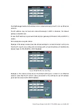
The parameters to enter are the nominal network voltage, network frequency and
inverter synchronization mode. The inverter synchronization mode shall normally
not be changed unless specifically instructed by the ABB service provider.
−
The inverter characteristics (Cf.
Section 7.9.3.2
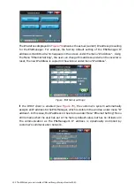
This consists of setting up the inverter connection mode: 3-wire (no neutral
connected) or 4-wire (neutral connected).
When the connection mode selected in the commissioning menu does not
correspond to the hardware set-up detected by the inverter, the unit will trip out
when started. A ‘Bad Parameters’ fault will be reported in the inverter event log.
Correct the problem before proceeding.
−
The CT settings:
The CT settings can in many cases be automatically detected or can be entered
manually.
Section 8.6
discusses the automatic and manual CT detection
procedure.
−
The Rating parameter:
If the inverter is installed at locations higher than 1000m /3300ft or is running
under ambient temperature conditions higher than 40°C/104°F, the inverter has
to be derated. For more information on how to calculate the derating required
and how to enter the derating value, refer to
Section 7.9.3.5
−
The battery limitations
According to the specification of the battery, limitations can be set in the inverter
control. These limitations are concerning the voltage (battery and cell),
temperature (battery and cell) and current (battery).
Remarks:
−
Although the user requirements can be set up from the commissioning window
this should not be done before the system has been started successfully for the
first time (Cf.
Section 8.7
−
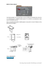
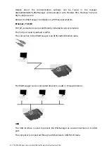
If digital I/O and/or the alarm contact have been cabled on the ESI-Manager, the
appropriate software settings have to be made. This has to be done in the
‘Customer settings’ menu ([/Welcome/Settings/Customer set.]). Refer to
Section 7.9.2.4
for detailed information on how to set up digital I/O, alarms and
warnings. In order to achieve full redundancy with master-master inverters, the
digital I/O have to be cabled to all master units and all the ESI-Managers have to
be set up accordingly.
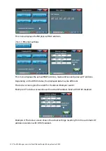
−
In order to change the temperature unit used by the system, go to
[/Welcome/Settings/Customer set./Temp unit].
−
For setting up advanced inverter functions such as the autorestart feature (after
power outage), the inverter standby feature (which stops the IGBTs when the
load requirement is low), the system clock, the external communication protocol
(Modbus or PC) and the software lock, refer to
Section 7.9.4
In order to achieve