Manual Energy Storage Inverter ESI-S
The ESI-Manager user interface 99
7.8.2.3.1 Waveforms
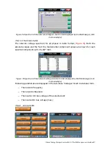
The inverter current waveforms for all phases for the unit selected with the ‘Select unit’
option. The graph layout is similar to the one of the voltages (
). All waveforms
are synchronized with the rising edge zero crossing of the voltage V (L1-N) (4-W mode)
or V (L1-L2) (3-W mode).
7.8.2.3.2 Spectrum
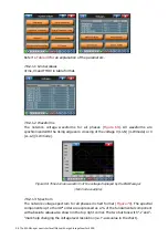
The inverter current spectrum for all phases (3-W mode) and the neutral current
spectrum (4-W mode) in chart format for the unit selected with the ‘Select unit’ option.
The chart layout is similar to the one of the voltages (
expressed in absolute terms.
7.8.2.3.3 Harmonic table
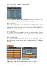
The inverter current spectrum for all phases (3-W mode) and the neutral current
spectrum (4-W mode) in table format for the unit selected with the ‘Select unit’ option.
The table layout is similar to the one of the voltages (
) but only absolute current
values are shown.
7.8.2.4 Total inverter currents
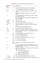
Refer to
for an explanation of the parameters.
ESI Irms in table format for the complete inverter system.
7.8.2.4.1 Waveforms
The inverter current waveforms for all phases for the complete inverter system. The
graph layout is similar to the one of the voltages (
). All waveforms are
synchronized with the rising edge zero crossing of the voltage V (L1-N) (4-W mode) or V
(L1-L2) (3-W mode).
7.8.2.4.2 Spectrum
The inverter current spectrum for all phases (3-W mode) and the neutral current
spectrum (4-W mode) in chart format for the complete inverter system. The chart layout
is similar to the one of the voltages (
) but the values are expressed in absolute
terms.

