Manual Energy Storage Inverter ESI-S
Electrical design and installation 59
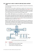
L1
L2
L3
Load side
Supply side
K
L
K
L
K
L
ESI
L1
L2
L3
To X21.2
To X21.5
To X21.8
K = P1, L = P2, k = S1, l = S2
N
N
X21.1
X21.2
X21.3
X21.4
X21.5
X21.6
X21.7
X21.8
X21.9
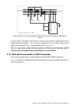
Figure 44: Four wires CT wiring approach that may be used with a single unit ESI-S active
inverter
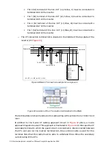
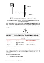
In case a system consists of more than one unit, all units have to be supplied with the CT
measurement information. This is done by cabling the CTs in a daisy chain fashion
between the different units. This is illustrated in
Note: in case power quality features (harmonics filtering, load balancing and PF
correction) are not required above mentioned CT’s are not needed.
6.13 Electrical interconnection of ESI-S enclosures
This section explains how to electrically interconnect different ESI-S enclosures.
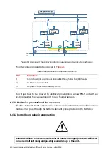
shows schematically which interconnections have to be made between two
inverter enclosures.


