Manual Energy Storage Inverter ESI-S
Troubleshooting guide 209
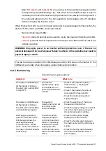
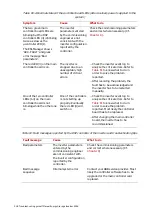
Fault message
Cause
What to do
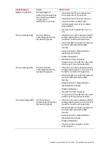
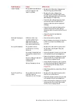
Bad CT connection
The automatic CT
detection procedure has
encountered a problem
during the CT
identification process.
−
Check that the CTs are installed on
the supply side of the inverter.
−
Check that the CTs are not shorted.
−
Check that the overall CT ratio
(including summing CTs) is smaller
than 20000/5.
−
Set up the CTs manually (Cf.
Section
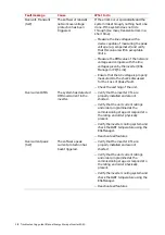
DC overvoltage (SW)
The DC software
overvoltage protection
has been triggered.
−
Check the connection between the DC
voltage measurement connector (P6-
5 and P6-7) and the DC capacitors.
−
Check flat cable connections between
the Control Board and the IGBT
module.
−
Analyze network voltage stability
(amplitude and phase).
−
Disable all features
−
Deselect the high frequency
components to free DC bus resources
and to see if the problem persists.
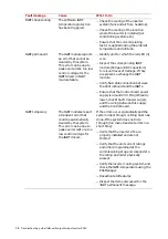
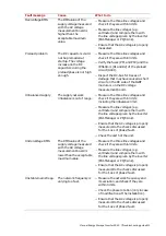
DC overvoltage (HW) The DC hardware
overvoltage protection
has been triggered.
−
Check the connection between the DC
voltage measurement connectors (P6-
5 and P6-7) and the DC capacitors.
−
Check flat cable connections between
the Control Board and the IGBT
module.
−
Analyze network voltage stability
(amplitude and phase).
−
Disable all features
−
Deselect the high frequency
components to free DC bus resources
and to see if the problem persists.
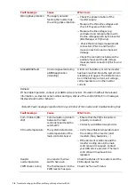
DC undervoltage (SW) The DC software
undervoltage protection
has been triggered.
−
Check the connection between the DC
voltage measurement connectors (P6-
5 and P6-7) and the DC capacitors.
−
Check flat cable connections between
the Control Board and the IGBT
module.
−
Analyze network voltage stability
(amplitude and phase).
−
Disable all features
−
Check the main contactor and its
control signal.

