Manual Energy Storage Inverter ESI-S
The ESI-Manager user interface 111
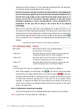
Table 44: Reactive power tasks that the inverter can perform
Reactive power task requirement
Description and inverter set-up to be made
No requirements
PFC type: Disabled
Balance load: Disabled
The inverter will not do any reactive power task,
regardless of the values set for cos
ϕ
or static
reactive power
Power factor compensation with
inductive power factor set point, no
load balancing required
(a)
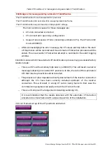
PFC type: Dyn. Ind.
Target cos
ϕ
: Desired power factor between 0.6 and
1.0
The inverter will do power factor compensation up to
the cos
ϕ
set point, regardless of the value set for
static reactive power
(b)
Power factor compensation with
capacitive power factor set point, no
load balancing required
(a)
PFC type: Dyn. Cap.
Target cos
ϕ
: Desired power factor between 0.6 and
1.0
The inverter will do power factor compensation up to
the cos
ϕ
set point, regardless of the value set for
static reactive power
(c)
Fixed capacitive power step with a
rating of x kvar, no load balancing
required
(a)
PFC type: Static cap.
Q static: x kvar
The inverter will generate x kvar reactive capacitive
power, regardless of the value set for the target cos
ϕ
Fixed inductive power step with a
rating of x kvar, no load balancing
required
(a)
PFC type: Static ind.
Q static: x kvar
The inverter will absorb x kvar reactive inductive
power, regardless of the value set for the target cos
ϕ
Remarks:
(a)
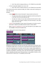
When load balancing is required, set the ‘
Balance load’ flag to the desired mode. The following
modes are available depending on the way the inverter is connected
(3-W or 4-W)
-
‘Disabled’: No load balancing is done.
-
‘L-L’: Loads connected between phases only are balanced. Loads connected between
phases and neutral are not balanced.
-
‘L-N’: Loads connected between phase and neutral are balanced. Loads connected
between phases are not balanced. This mode is only available when the inverter is
connected in 4-W mode.
-
‘L-L & L-N’: Both loads connected between phase and neutral as well as loads connected
between phases are balanced. This mode is only available when the inverter is connected
in 4-W mode.
Note: The modes ‘L-N’ and ‘L-L & L-N’ can be used to minimize the amount of fundamental
frequency current flowing in the neutral.
(b)
If the measured cos
ϕ
is higher than the set point and is inductive (e.g. measured 0.97
inductive and set point 0.92 inductive, then the inverter will not make any correction. If the
measured cos
ϕ
is capacitive, the inverter will correct the power factor to 1.0

