Manual Energy Storage Inverter ESI-S
Electrical design and installation 53
Remarks:
The minimum DC voltage for the battery is defined by the following formula:
=
2. .
√
2
. Where V is the phase to neutral network voltage.
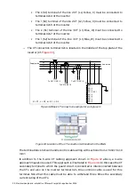
In case of regenerative loads (e.g. loads that may inject active energy to the network,
usually called 4Q-loads), it is very important to connect the ESI outside the protection of
this load. Indeed, consider
where a common protection is installed for both
the regenerative load and for the ESI. When the load re-injects energy to the network and
the mains protection trips, the whole energy may be pushed into the ESI, which may
damage it severely.
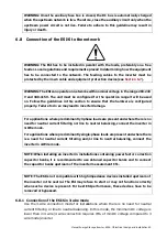
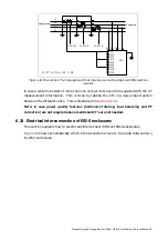
shows the admitted protection scheme for regenerative
loads. In this case, if the breaker of the load trips, the ESI is isolated from the energy fed
back by the drive.
ESI
4Q
load
ESI
4Q
load
Figure
38:
Incorrect
connection
Figure
39:
Correct
connection
in
the
case
of
4Q-loads
in
the
case
of
4Q-loads
6.9 Connection control the DC switch
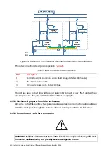
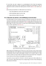
The ESI-S is not connected directly to the battery, a DC switch has to be installed
between the ESI-S and the battery. The DC switch is driven by the inverter. The command
of the DC switch has to be connected to the X5-1 and X5-2 connectors in the inverter. The
output voltage from the inverter for the contactor command is 230V V
ac
. The table below
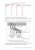
is giving the max DC current allowed for ESI-S.
Inverter nominal AC
current rating (Arms)
Power rating (kVA)
Max DC current (A)
30
20
37
45
30
56
60
40
74
70
50
86
80
55
98
90
60
111
100
70
123
120
85
147


