


184 Operating instructions
Manual Energy Storage Inverter ESI-S
−
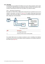
If the hardware lock and/or the Communication lock has/have been engaged, the
inverter cannot be started nor stopped neither by the local button nor by remote
control. In order to see which lock(s) has/have been engaged push
when
the ‘start/stop’ menu is highlighted. A message will appear to indicate which
lock(s) has/have to be disengaged. If authorized, disengage the relevant lock.
•
The hardware lock can be disengaged by pushing the blue button present
at the bottom rear of the ESI-Manager. More information on the inverter
menu locking facilities is given in
Section 7.6
•
The Communication lock can be engaged in the menu [/Welcome/User
interface/Communication] by ticking the “check box”. More information
on the Communication lock is available in the document
“2GCS212013A0050-RS-485 Installation and Start-up guide”.
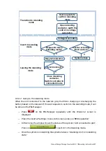
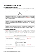
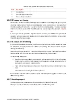
The stop sequence conducted when a stop command is given can be derived from the
following flow chart.
System is running
Stop request
Stop IGBT’s
Open the DC
contactor
Controller
running,
DC capacitors
charging, wating
for a start request
Open the AC
contactor
Figure 93: inverter operation sequence when no fault is present
The DC bus incorporates discharge resistors that can discharge the DC bus in 25 minutes
once the supply is open.
9.3 Modifying the user requirements
9.3.1 Active and reactive power targets
Power targets (P and Q) can set soon as the system is connected to the battery. The sign
convention is described in the table below. Since the inverter is defined in kVA, both