66 Electrical design and installation
Manual Energy Storage Inverter ESI-S
In a multi-master arrangement, the master that has the control over the system (i.e. the
master which is operational and which has the lowest address) will monitor the digital
inputs. Therefore, in order to obtain full redundancy with inverters consisting of more
than one master unit, the digital inputs of all the units in a multi-master arrangement
have to be set up and cabled in the same way.
Remarks:
−
When the remote control functionality has been activated this function has
priority over a local start/stop command. When the local command has to be
given, deactivate first the remote control functionality by navigating with the
ESI-Manager to the digital input setup menu and setting the digital input
considered to ‘Disabled’.
−
The remote control functionality can also be implemented on the Digital Input 2.
6.14.2 Cabling of alarm functionality
An alarm represents an error condition that makes the inverter trip.
Two types of error conditions exist:
1. External error condition: These are conditions that are imposed on to the inverter
from the outside world. Consider the example of the network voltage that increases
well above the inverter safe operation level for a certain time. In that case the inverter
will disconnect from the network reporting a network over voltage. When the
network voltage returns to a normal level however, the inverter will reconnect to the
network and continue filtering providing that the same problem does not occur
systematically.
2. Internal error conditions: These are error conditions that are reported by internal
controls of the inverter itself. They may indicate an internal inverter problem.
Two ways to cable the alarm functionality exist:
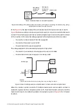
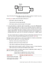
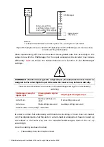
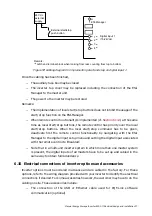
1. The ESI-Manager alarm outputs located at the bottom right side (when looking at the
ESI-Manager from the rear) are triggered (return to default position) whenever:
−
A permanent internal or external error condition is present. In order to avoid
transient switching of the contacts, the error has to be present for 3 minutes
before the alarm relays are activated.
−
No power is supplied to the inverter
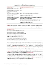
further down this section gives an overview of all the error conditions that lead
to the alarm contact being triggered. Two alarm contacts exist, one being of type
‘normally open’ (NO) and the other of type ‘normally closed’ (NC).
The alarm contacts are
−
Free of potential
−
Rated for a maximum of 250 Vac/1.5 A or 30 Vdc/5 A. When using a
24 Vdc power supply, a minimum current of 25 mA should be drawn by the circuit
connected to the alarm contact.


