


Manual Energy Storage Inverter ESI-S
Hardware description 17
3
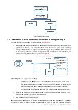
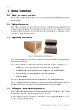
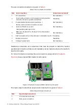
Auxiliary fuse protection
4
ESI-Manager user interface with connection terminals for user I/O (e.g. alarm
contact) and communication interfaces
5
Neutral connection
6
Battery connection
Up to 8 ESI-S master panels can be connected in parallel providing full redundancy to the
customer.
In addition to using master panels only, ESI-S units can be connected in a master-slave
arrangement.
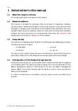
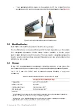
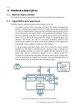
4.3 The ESI current/voltage generator hardware
The power circuit of an ESI-S unit is represented hereafter.
Preload
circuit
IGBT
inverter
N
L
AC power supply
1
2
9
7
5
6
8
Output
filter
4
3
Figure 12: Power circuit diagram of an ESI-S inverter
The description of the main components is given in
Table 5: Main components of an ESI-S inverter
Item
Main
components
1
IGBT inverter
2
DC bus capacitors
3
PWM reactor
4
Output inverter