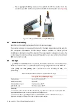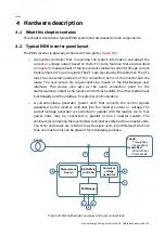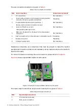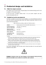
20 Hardware description
Manual Energy Storage Inverter ESI-S
An ESI-S inverter system consists of up to 4 units of equal rating. Additional units to the
first master unit may be master or slave units. Slave units do not have an ESI-Manager.
4.5 The ESI-Manager user interface
All user interaction with the inverter is channeled through the ESI-Manager.
In multi-unit system consisting of only one master, only the master has an ESI-Manager.
In multi-unit system consisting of more than one master, all the master units have an
ESI-Manager. However, only the ESI-Manager that is connected to the master unit which
has the overall control will be active. The ESI-Manager installed on the units operating as
"slaves" are capable of displaying the relevant information about that specific unit only.
Certain parameters which are specific to that unit (e.g. related to temperature probes)
can be set or changed locally using the ESI-Manager installed on that unit. The ESI-
Manager on the master unit has a "unit selection"
button which allows the user to
select the unit number which he wants to consult. The data then displayed on the master
ESI-Manager is specific to that particular unit number. This unit selection button is
"deactivated" on the slave Managers.
shows the front side of the ESI-Manager.
Figure 14: Front side of the ESI-Manager
Five main parts can be distinguished (see
Table 6: Front side of the ESI-Manager
Item Description
1
Menu display
By
navigating
through
the
menus
with
the
,
,
and
buttons, the inverter can be set-up and controlled
.
On-line help is available by
pressing
the button.
2
Master/slaves units monitor

