


Manual Energy Storage Inverter ESI-S
Electrical design and installation 51
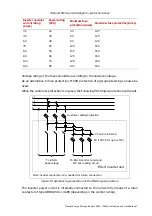
−
The right reactor terminal corresponds to phase L3 (B, C)
−
The cable lugs of the feeding cables should comply with:
•
Maximum lug width: in accordance with terminal width
•
Minimum lug eye diameter: M8
−
Appropriate torque (20Nm) must be applied to ensure that cables are properly
fixed.
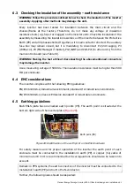
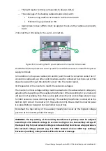
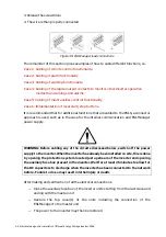
7. Connect the 2 DC cables to the + and – connectors.
+
-
Figure 35: Connecting the DC power cables to the inverter DC terminals
8. Slide the bottom protective cover up and fix it with the screws to seal off the power
supply terminals
9. In addition to the power cables (AC and DC) and the earth connection cable, the CT
connection cable and any other control cables used for enhanced functions can at this
stage be passed through the protective cover into the inverter panel.
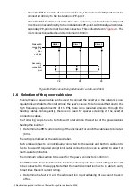
10. Preparation of the inverter to match the networks voltages:
The inverter nominal voltage setting must be adapted to the actual network voltage by
adjusting the tap setting of the auxiliary transformer. If the tap setting for your network
voltage is not available, then choose a tap just above the network voltage present (e.g.
for 390V network choose 400V tap setting). The auxiliary transformer is situated at the
bottom right side of the inverter (Cf. Figure 16, item 15). Ensure that the inverter panel
is isolated before changing the transformer tap setting.
By default the tap setting of the auxiliary transformer is set at the highest voltage
position at the inverter production stage.
WARNING: The tap setting of the auxiliary transformer’s primary must be adapted
according to the network voltage to avoid a too high or too low auxiliary voltage. If
the tap setting for your network voltage is not available, then choose a tap just above
the network voltage present (e.g. for 390V network choose 400V tap setting).
Excessive (auxiliary) voltage levels will lead to inverter damage.


