


82 The ESI-Manager user interface
Manual Energy Storage Inverter ESI-S
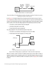
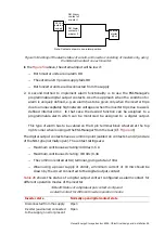
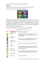
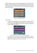
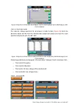
The module status indicator: there are 8 numbered icons present on the left bottom of
the screen, each representing a power module. The active modules are displayed in blue
color; the faulty ones in red and those modules which are not present are greyed.
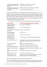
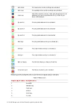
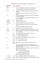
Table 34 Module status icons
Icons
Status
Ready: the unit considered does not have a fault and can run normally
Fault: the unit considered has been stopped due to an error. By pressing Ack.
Fault, the reason for the fault will be displayed and an attempt will be made
to clear the fault. When doing this, the complete inverter system will be shut
down. If the fault could be cleared, the unit status will become ‘ready’. If the
fault could not be cleared, the unit status will remain ‘Ack. Fault’. In the fault
clearing process, the complete inverter system will be shut down. The
inverter can be restarted after the fault clearing process has ended.
Not present: the unit considered has been excluded of the normal inverter
operation due to either fault or the unit is not present
Master
An alarm icon showing when the ESI-Manager’s alarm contact has been activated
(Cf.
) changes its appearance when the alarm condition exists. When the alarm
condition has disappeared, the respective alarm icon takes back the normal appearance.
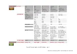
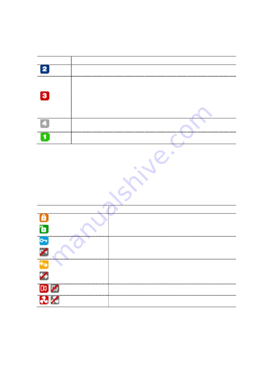
The status of protection (locked/unlocked) is also displayed by a dedicated icon.
Hardware lock and software locks have separate icons.
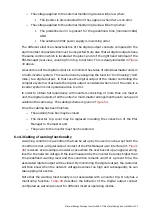
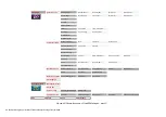
Table 35 Alarm/lock status icons
Icons
Status
Software lock
Software unlock
Hardware lock
Hardware unlock
Communication lock status
Communication unlock status
Alarm status
Fan status
Alarms
Programmed alarm can:
−
activate any digital output relay 1-6 if selected
−
activate global alarm NO/NC relay