


Manual Energy Storage Inverter ESI-S
Hardware description 21
3
Locking status / Alarm and fan contact indicator / Digital output contact indicator
When the ESI-Manager closes one of its output relays, the corresponding symbol
lights up. The digital outputs of the ESI-Manager are discussed later in this section.
4
unit
selection
5
Start
stop
acknowledgment
fault
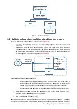
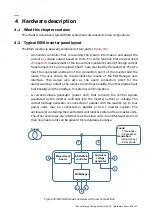
The ESI-Manager also acts as connection point for external user I/O communication.
Connections are made at the rear side of the ESI-Manager.
depicts the
terminals that are present on the ESI-Manager rear side.
1
2
3
4
5
6
7
8
9
10
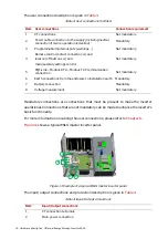
Figure 15: ESI-Manager rear side terminal designation
The terminal designation is given in
Table 7: Terminal designation
Item
Customer terminals
1
Digital input 1 and 2
2
Digital outputs 1 to 6 with one common point
3
Alarm outputs (2 outputs with complementary signals) and fan outputs
4
Lock switch
5
Modbus adapter interface (optional) connection
6
CAN bus connection interface (routed to ESI-Manager connector)
7
Power supply terminals (routed to ESI-Manager connector)
8
Ethernet
9
USB
10
Temperature probes