


Manual Power Quality Inverter ESI-S
The ESI-Manager user interface 81
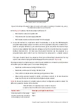
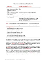
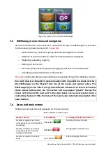
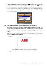
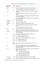
Figure 60 Main screen of the ESI-Manager
7.3 ESI-Manager overview and navigation
All user inter-action with the inverter is channeled through the ESI-Manager. It provides
for the following main functions (Cf
.
−
Inverter starting, inverter stopping and acknowledgement of faults
−
Selection of power module for which the relevant data is displayed
−
Measuring, analyzing, logging
−
Setting up the inverter
−
Monitoring the inverter load, event logging and status of individual units
−
Providing inverter identification information
outlines the principle menus that are accessible through the ‘Welcome’ screen.
In a multi master configuration (several master units in parallel in a single inverter),
the ESI-Manager on the “Master” unit has all the menus and options active. The
ESI-Manager(s) on the “Slave” unit(s) have different screens in the sense that certain
items (menu, buttons etc.) are “non-active” and may appear “greyed”. In case the
maser unit fails and the next unit in the order takes over as new master (due to
redundancy feature of ESI), the menu of the new master automatically adapts to this
new situation.
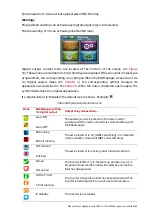
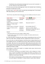
7.4 Icons and main screen
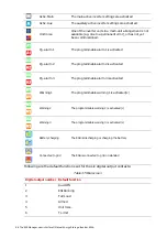
Following icons and menu are present on the main screen:
Table 33 Inverter status icons
Inverter status
Menu display
Touching the button results in …
Inverter stopped, no critical
error present (i.e. ‘normal’ stop
condition)
ESI START
Starting the inverter unit
Inverter running, no critical
error present (i.e. ‘normal’
running condition)
ESI STOP
Stopping the inverter unit
Inverter stopped on critical
fault
ACK. FAULT
Acknowledging the fault