


72 Electrical design and installation
Manual Energy Storage Inverter ESI-S
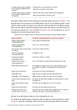
Table 28: State of a digital output contact configured as
warning contact for different inverter operation modes
Inverter state
Normally open digital contact state
Disconnected from the supply
Open
Inverter (auxiliaries) connected
to the supply, no warning
present
Open
Inverter (auxiliaries) connected
to the supply, predefined
warning present
Closes when warning present for predefined time
Otherwise, contact remains open
Inverter (auxiliaries) connected
to the supply, predefined
warning disappears
When closed before and warning disappears for at least the
predefined time, contact opens.
When closed before and warning disappears for a time
smaller than predefined time, contact remains closed.
Otherwise, contact remains open.
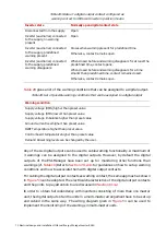
gives a list of the warning conditions that can be assigned to a digital output.
Table 29: List of possible warning conditions that can be assigned to a digital output
Warning condition
Supply voltage (RMS) higher than preset value
Supply voltage (RMS) lower than preset value
Supply voltage imbalance higher than preset value
Ground current level higher than preset value
IGBT Temperature higher than preset value
Control board temperature higher than preset value
Remark: All warning levels can be changed by the user.
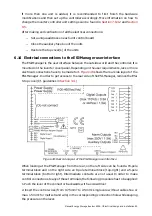
Any of the six digital outputs can be used to cable warning functionality. A maximum of
3 warnings can be assigned to the digital outputs. However, by default the digital
outputs of the ESI-Manager have been set up for monitoring other functions than
warnings (cf.
) Refer to
Section 7.9.2.4.1
for guidelines on how to set up warning
conditions and how to associate them with digital output contacts.
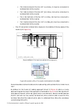
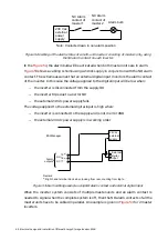
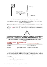
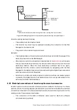
For cabling the digital output contacts as warning contact, the same approach as shown
in
can be adopted. The electrical characteristics of the digital output contacts
and the points to pay attention to are discussed in
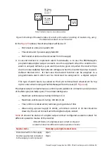
In order to obtain full redundancy with inverters consisting of more than one master
unit, the digital outputs of all the units in a multi-master arrangement have to be set up
and cabled in the same way. The wiring diagram given in
can be used to
implement the monitoring of the warnings in multi-master units.