


22 Hardware description
Manual Energy Storage Inverter ESI-S
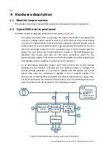
The terminal explanation is given next:
1
Digital input 1 and 2
The digital inputs can be used for three different functions:
−
Implementation of remote control functionality;
−
Implementation of local on/off buttons (not provided);
−
Selection of main inverter settings or auxiliary inverter settings (e.g. different
inverter settings for the day and for the night).
The ESI-Manager is used to associate the required functionality with the chosen digital
input. The digital inputs can also be disabled.
WARNING: If a function is assigned to a digital input, the same function must never be
assigned to the other digital input. Otherwise the inverter may behave erratically.
The external voltage source needed to drive the digital inputs has to comply with the
following characteristics:
−
Vlow: 0 Vdc
−
Vhigh: 15-24 Vdc
−
Driving current: 13 mA @ 24 Vdc (Rint = 1.88 k
Ω
)
The digital inputs have free of potential contacts (opto-isolated).
When implementing any of the functions described above, please note that according to
the setup done with the ESI-Manager for the input considered, the inverter may behave
differently.
below gives an overview of the possible settings and the resulting
inverter behavior.
Table 8: Overview of possible digital input settings and resulting inverter behavior
Function
Vlow applied
to digital
input
Vhigh applied to digital
input
Remote control
ESI-Manager setup for digital input: Remote
ON
(a)
inverter
off
inverter
on
Selection of main/auxiliary settings
ESI-Manager setup for digital input: Activ.
Main
(a)
Auxiliary
settings are
used
Main settings are used
Selection of main/auxiliary settings
Main settings
are used
Auxiliary settings are used