


Manual Energy Storage Inverter ESI-S
Hardware description 25
6
T Limit
−
The customer can change the default output settings by means of the
ESI-Manager.
−
The digital outputs contacts have a common point and are of the NO-type
(normal open). The contact ratings are:
•
Maximum continuous ac rating: 440 Vac/1.5 A;
•
Maximum continuous dc rating: 110 Vdc/0.3 A;
•
The common is rated at 9A/terminal, giving a total of 18 A.
Information on cabling the digital output contacts is given in
Information on setting up the digital outputs with the ESI-Manager is given in
Section
3
Alarm outputs and fan outputs
Apart from the digital outputs, one potential free relay with a NO and a NC alarm output
is available. This relay contact is activated if any error condition is present during a
preset time. The relay contact is deactivated if the error condition has disappeared for
another preset time. Information on changing the alarm activation/deactivation time is
given in
Section 7.9.2.4.1
In a master-master arrangement, only the master that has the control over the complete
system will activate its alarm contact. For full redundant functionality, it is
recommended to monitor the alarm contacts of all the units in the system.
The maximum continuous alarm contact ratings are: 250 Vac/1.5 A.
A fan relay can be activated if a temperature probe detects an overtemperature.
4
Lock switch
Allows locking the settings of the inverter panel. This switch is documented in
Section
5
Modbus RTU adapter interface (optional) connection
The Modbus adapter interface is connected at this location. The output of the interface
is an RS-485 socket. The interface is described in the Modbus RTU interface manual.
6
CAN bus connection interface
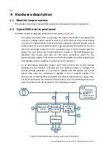
The ESI-Manager communicates with the main controller through a CAN bus. This bus
consists of three terminals, i.e.:
−
Pin H: CAN High signal
−
Pin L: CAN Low signal
−
Pin Shield: shielding