Manual Energy Storage Inverter ESI-S
Electrical design and installation 63
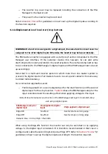
If more than one unit is added, it is recommended to first finish the hardware
modifications and then set up the controller accordingly. More information on how to
change the inverter controller unit settings can be found in
Section 7.9.3.2
and
Section
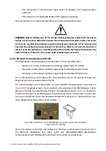
After making and verification of all the electrical connections:
−
Set a unique address on each unit control board
−
Close the auxiliary fuse box of the units
−
Restore the top cover(s) of the units
6.14 Electrical connections to the ESI-Manager user interface
The ESI-Manager is the user interface between the outside world and the controller. It is
mounted on the inverter cover panel. Depending on the user requirements, less or more
electrical connections have to be made to it.
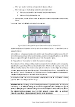
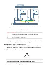
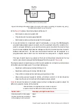
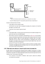
shows the rear side layout of the
ESI-Manager. In order to get access to the rear side of the ESI-Manager, remove the ESI-
S top cover (Cf. guidelines in
)
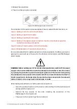
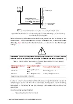
Figure 48: Rear side layout of the ESI-Manager user interface
When looking at the ESI-Manager from the rear, on the left side can be found a 15-pole
terminal block and on the right side an 8 pole terminal block (top-right) and a 5-pole
terminal block (bottom right). Intermediate contacts are not used. In order to make
control connections to any of these terminals, the following procedure has to be applied:
1. Push the lever of the connector backwards with a screwdriver
2. Insert the control wires (from 0.75 mm² to 2.5 mm² single core without cable shoe or
max. 1.5 mm² for multi-strand wire) in the corresponding connection hole while keeping
the pressure on the lever.

