


76 Electrical design and installation
Manual Energy Storage Inverter ESI-S
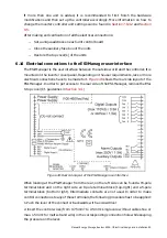
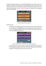
The electrical requirements of the digital inputs are as discussed in
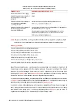
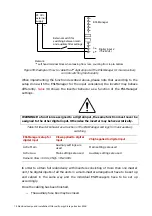
shows a cabling diagram for implementing a start function on the first digital input
and a stop function on the second digital input.
External
stop push
button
24 Vdc
external
supply
+
-
1
(a)
2
(a)
3
(a)
4
(a)
ESI-Manager
Digital input 1 (15-24Vdc)
Digital input 2 (15-24Vdc)
Remark:
(a)
Left hand terminal block when looking from rear, counting from top to bottom
External
start push
button
Figure 56: Cabling diagram for implementing start on digital input 1 and stop on digital input 2
−
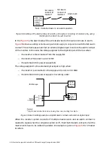
The second approach is to use one digital input for both the start function and
the stop function. This leaves the other digital input available for the
implementation of other functions.
shows the ESI-Manager setup for the input considered and the resulting effect
when applying voltage to this input.
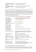
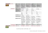
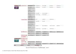
Table 32: Inverter behavior as a function of the ESI-Manager settings for local start/stop and
using 1 digital input
ESI-Manager setup
for digital input
Vlow applied to
digital input
Vhigh applied to digital input
Edge ON/OFF
No effect
Inverter starts on first rising edge, stops on
second rising edge, etc
Remark: Vlow = 0 Vdc, Vhigh = 15-24 Vdc
Refer to
Section 7.9.2.4.2
for guidelines on how to set up the digital inputs according to
the function required.
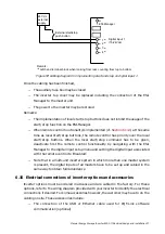
The electrical requirements of the digital inputs are as discussed in
shows a cabling diagram for implementing a start function and a stop function on the
first digital input.


