Manual Energy Storage Inverter ESI-S
Hardware description 27
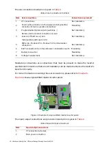
Figure 16: ESI-S main components
The component identification is given in
Table 11: ESI-S main components description
Item Description
Circuit diagram designation
1
Main
contactor (MC)
(underneath
controller boards)
K01
2
Fuse holder auxiliaries circuit
Q02
3
DC voltage power supply 24V
U002
4
CT
connection
terminal
X21
5
Preload
circuit
rESI-Stors
R1, R2
6
Main earth connection point
-
7
IGBT inverter with DC capacitors
U01
8
ESI main controller board
A005
9
IGBT heat extraction fans
M1, M2
10
PCB
EMC
neutral
A003
11
PCB
EMC
line
A002
12
PCB output inverter preload
A001
13
Main power supply terminals (phases)
(underneath controller boards)
L1, L2, L3
14
Main power supply neutral connection (not
mandatory) (underneath controller boards)
N
15 Auxiliary
transformer
T001
16
Fuse
preload
circuit
PF1, PF2
17
Measurement board (DC current and AC
voltages)
18
DC power connection (underneath
controller boards)
19
DC
current
measurement

