


60 Electrical design and installation
Manual Energy Storage Inverter ESI-S
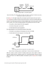
Preload
circuit
IGBT
inverter
N
L
AC power supply
1
Output
filter
Preload
circuit
IGBT
inverter
Output
filter
2
3
3
DC+
DC-
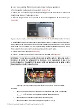
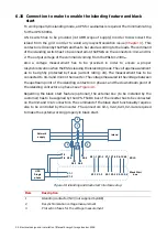
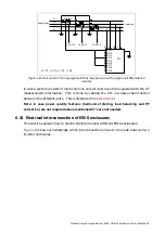
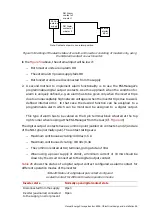
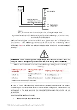
Figure 45: Overview of the connections to be made between two inverter enclosures
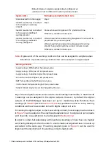
The interconnection description is given in
Table 24: Interconnections between two units
Item Description
1
Control board intercommunication cable through CAN bus (RJ45 cable)
2
CT interconnection cable
3
DC power connection to battery DC bus
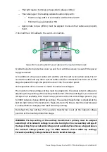
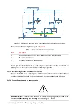
Four steps have to be followed to electrically interconnect a new ESI-S unit with an
existing inverter. They are outlined in the next four paragraphs.
6.13.1 Mechanical preparation of the enclosures
All cables to the ESI-S unit such as power cable as well as interconnection cable between
modules must pass through the bottom cable entry hole provided in the ESI-S box.
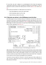
6.13.2 Control board cable interconnection
WARNING: Failure to interconnect the control boards in an appropriate way will result
in inverter malfunctioning and possibly severe damage of the unit.