11 SVR Virtual Motion Module
11.3.2 Motion Command Details
11-24
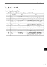
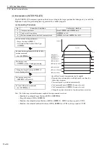
(4) Interpolation (INTERPOLATE)
The INTERPOLATE command positions the axis according to the target position that changes in sync with the
high-speed scan. The positioning data is generated by a ladder program.
(a) Operating Procedure
Note: The following position information is updated during command execution.
• Machine Coordinate Target Position (TPOS) (IL
OE)
• Target Position (CPOS) (IL
10)
• Machine Coordinate System Position (MPOS) (IL
12): MPOS is always equal to CPOS.
• Machine Coordinate Feedback Position (APOS) (IL
16): APOS is always equal to CPOS.
No.
Execution Conditions
Confirmation Method
1
There are no alarms.
Both IL
02 and IL
04 are 0.
2
The Servo ON condition.
IB
001 is ON.
3
Motion command execution has been completed.
IW
08 is 0 and IB
090 is OFF.
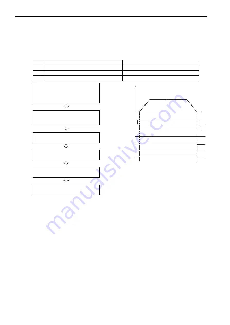
Set the motion setting parameters.
• Target Position: OL
1C
• Acceleration/Deceleration Filter Type:
OW
03
• Speed feed forward compensation can be applied.
• Generate the positioning data each high-speed scan from the
ladder logic program.
• The travel speed is calculated automatically.
• The Command Pause (OB
090) cannot be used.
• The Command Abort (OB
091) cannot be used.
• Change the motion command to stop interpolation execution.
Execute the interpolation (INTERPOLATE)
motion command.
• Set OW
08 to 4.
Positioning starts.
• IW
08 will be 4 during positioning.
Change the Target Position (OL
1C)
every high-speed scan.
Positioning completed.
• IB
0C1 will turn ON.
Execute NOP motion command.
• Set OW
08 to 0.
Position
0
Speed (%)
Time (t)
OW
08 = 4
(INTERPOLATE)
IW
08 = 4
(INTERPOLATE)
IB
090 (BUSY)
IB
098 (COMPLETE)
IB
0C0 (DEN)
IB
0C1 (POSCOMP)
IB
0C3 (NEAR)

