background image

11.2  Motion Parameters

11-5

11

11.2  Motion Parameters

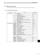
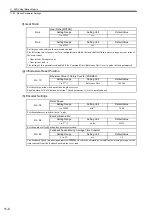
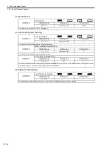
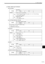
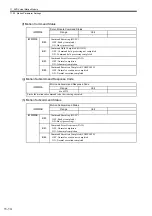
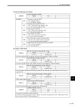
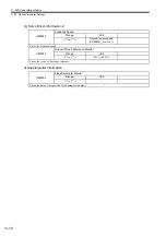
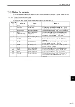
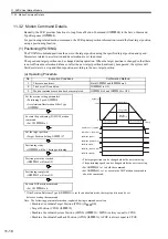
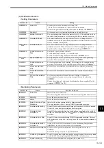
The following table gives motion parameters used by the SVR and the default values of the parameters. 

11.2.1  Motion Parameter Details

Type

No.

Name

Default Value

Fixed Parameters

0

Run Mode

1

1

Function Selection 1

0000 Hex

4

Command Unit

0

5

Number of Decimal Places

3

6

Command Unit per Revolution

10,000

8

Gear Ratio [MOTOR]

1

9

Gear Ratio [LOAD]

1

10

Maximum Value of Rotary Counter (POSMAX)

360,000

34

Rated Speed

3,000

36

Encoder Resolution

65,536

42

Feedback Speed Moving Average Time Constant

10

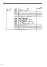
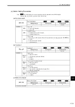
Setting Parameters

OW

††

00

Run Commands

0000 Hex

OW

††

03

Function 1

0011 Hex

OW

††

08

Motion Command

0

OW

††

09

Motion Command Options

0000 Hex

OW

††

0A

Motion Subcommand

0

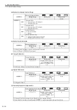
OL

††

0C

Torque Reference

0

OL

††

10

Speed Reference

3,000

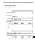
OL

††

16

Secondly Speed Compensation

0

OL

††

1C

Position Reference Type

0

OW

††

31

Speed Amends

0

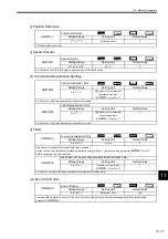
OL

††

36

Linear Acceleration Time

0

OL

††

38

Linear Deceleration Time

0

OW

††

3A

S-Curve Acceleration Time

0

OW

††

3B

Bias Speed for Exponential Acceleration/Deceleration 
Filter

0

OW

††

3D

Home Window

100

OL

††

44

Step Distance

1,000

OL

††

48

Zero Point Offset

0

OL

††

4A

Work Coordinate System Offset

0

OL

††

4C

Preset Data of POSMAX Turn

0

OL

††

5C

Fixed Parameter Number

0
Содержание MP2100 Series

Страница 1: ...YASKAWA YASKAWA MANUAL NO SIEP C880700 01C Machine Controller MP2100 MP2100M USER S MANUAL MODEL JAPMC MC2100 JAPMC MC2140 DESIGN AND MAINTENANCE...

Страница 2: ...liability is assumed with respect to the use of the information contained herein Moreover because Yaskawa is con stantly striving to improve its high quality products the information contained in this...

Страница 3: ...m Installation and Wiring Trial Operation Maintenance and Inspection Chapter 1 Overview Applicable Chapter 2 System Configuration Applicable Chapter 3 System Startup Applicable Chapter 4 Specification...

Страница 4: ...In this manual the names of reverse signals ones that are valid when low are written with a forward slash before the signal name as shown in the following example Copyrights S ON S ON P CON P CON Mic...

Страница 5: ...election methods ratings characteristics diagrams cables peripheral devices wiring panel installation trial operation adjustment function application methods maintenance and inspection of the II Serie...

Страница 6: ...ld possibly result in loss of life or serious injury Indicates precautions that if not heeded could result in relatively serious or minor injury damage to the product or faulty operation Indicates pro...

Страница 7: ...lectrical shock or injury Do not damage pull on apply excessive force to place heavy objects on or pinch cables There is a risk of electrical shock operational failure or burning of the MP2100 Do not...

Страница 8: ...dges and never touch the components or soldered connections Touching the components or leads can cause cuts or damage the MP2100 MP2100M or host computer In some computers it is necessary to secure th...

Страница 9: ...ns There is a risk of device damage Noise such as from static electricity Strong electromagnetic or magnetic fields Radiation Near to power lines When connecting the battery connect the polarity corre...

Страница 10: ...not change wiring while power is being supplied There is a risk of electrical shock or injury When replacing the MP2100 MP2100M restart operation only after transferring the programs and parameters f...

Страница 11: ...earance 1 5 2 System Configuration 2 1 MP2100 System Configuration 2 2 2 1 1 MP2100 Basic System Configuration 2 2 2 1 2 Precautions 2 2 2 2 MP2100M System Configuration 2 3 2 2 1 MP2100M Basic System...

Страница 12: ...rogram 3 Phase Control with an Electronic Shaft 3 50 3 4 1 Program Outline 3 50 3 4 2 Operation 3 51 3 4 3 Program Details 3 53 3 5 Sample Program 4 Phase Control with an Electronic Cam 3 55 3 5 1 Pro...

Страница 13: ...Mode 6 2 6 1 2 Offline Stop Mode 6 2 6 2 Startup Sequence and Basic Operation 6 3 6 2 1 MP2100 Mode Switch Settings 6 3 6 2 2 MP2100M Mode Switch Settings 6 4 6 2 3 Indicator Patterns 6 5 6 2 4 Startu...

Страница 14: ...1 Motion Commands 8 2 8 1 2 Motion Subcommands 8 3 8 1 3 Motion Command Support by SERVOPACK Model 8 4 8 2 Positioning POSING 8 5 8 3 External Positioning EX_POSING 8 10 8 4 Zero Point Return ZRET 8 1...

Страница 15: ...tion Function 10 2 10 1 1 Outline of the Function 10 2 10 1 2 Basic Terminology 10 2 10 2 Startup the Absolute Position Detection Function 10 3 10 2 1 System Startup Procedure 10 3 10 2 2 Setting Rela...

Страница 16: ...9 13 3 Motion Errors 13 18 13 3 1 Description of Motion Errors 13 18 13 3 2 Motion Error Details and Corrections 13 20 14 Application Precautions 14 1 Controlling a Vertical Axis 14 2 14 1 1 Overview...

Страница 17: ...a Motion Command is Started MP2100 MP2100M to SERVOPACK B 4 B 4 Parameters Updated at Self configuration SERVOPACK to MP2100 MP2100M B 4 B 5 Parameters Updated at Self configuration MP2100 MP2100M to...

Страница 18: ...he MP2100 MP2100M Machine Controller 1 1 MP2100 Overview 1 2 1 1 1 MP2100 Features 1 2 1 1 2 MP2100 Appearance 1 3 1 2 MP2100M Overview 1 4 1 2 1 MP2100M Features 1 4 1 2 2 Comparing SVB Motion Module...

Страница 19: ...ormance Control characteristics have been improved by increasing the CPU and Motion Network MECHA TROLINK II speed MECHATROLINK II baud rate 2 5 times faster MECHATROLINK II enables position control s...

Страница 20: ...1 1 MP2100 Overview 1 3 1 1 1 2 MP2100 Appearance The following figure shows the external appearance of the MP2100 I O YASKAWA MP2100 2 1 BAT BAT TX S2 S1 ON M I II...

Страница 21: ...ion Control of 0 5 ms The SVB Motion Module s MECHATROLINK port can be used on its own to control up to four axes using a 0 5 ms motion control cycle Set whether to use the two MP2100M ports SVB port...

Страница 22: ...1 2 MP2100M Overview 1 5 1 1 2 3 MP2100M Appearance The following figure shows the external appearance of the MP2100M MP2100M PORT2 M I II BAT TX S1 S2 PORT1 M I II I O BAT YASKAWA...

Страница 23: ...2 2 1 2 Precautions 2 2 2 2 MP2100M System Configuration 2 3 2 2 1 MP2100M Basic System Configuration 2 3 2 2 2 Precautions 2 3 2 3 Devices Connectable to MECHATROLINK 2 4 2 3 1 SERVOPACKs 2 4 2 3 2...

Страница 24: ...wa Yaskawa has a range of cables Always check the device to be used and select the correct cable for the device Different SERVOPACKs are connected to MECHATROLINK I and MECHATROLINK II Refer to the li...

Страница 25: ...SERVOPACKs If devices compatible with MECHATROLINK I 4 Mbps and with MECHATROLINK II 10 Mbps are used together make the all settings for MECHATROLINK I 4 Mbps When connecting SERVOPACKs via MECHATROL...

Страница 26: ...ws SERVOPACKs that are compatible with MECHATROLINK and can be connected to the MP2100 Model Number Details MECHATROLINK I MECHATROLINK II SGD N SGDB AN Series AC SERVOPACK for MECHATROLINK I Yes No S...

Страница 27: ...330 AC Output Module 100 200 VAC 8 outputs Yes No JAMSC 120DRA83030 Relay Module Wide voltage range relay contacts 8 contact inputs Yes No JAMSC 120AVI02030 A D Module Analog inputs 10 to 10 V 4 chann...

Страница 28: ...Battery for MP2100 MP2100M Module Connector Name Application Model Specifications MP2100 MP2100M I O External I O JEPMC W2062 I O External I O M I II MECHATROLINK I MECHATROLINK II cable JEPMC W6002...

Страница 29: ...nitializing the System 3 11 3 1 9 Starting the MPE720 3 14 3 2 Sample Program 1 Manual Operation 3 35 3 2 1 Program Outline 3 35 3 2 2 Operation 3 35 3 2 3 Program Details 3 38 3 3 Sample Program 2 Po...

Страница 30: ...2100 3 Installing the MP2100 Drivers Install the MP2100 drivers to the host computer 3 1 5 Installing the Drivers 4 Connecting and Wiring the System Wire the Servomotors and SERVOPACKs 3 1 7 Connectin...

Страница 31: ...PACK Servomotor Servomotor Terminator 200 VAC YASKAWA SERVOPACK 200V SGDS 01A12A SW1 CHARGE C N 3 A B C N 1 C N 2 C N 4 L1 L2 L2C L1C B1 B2 U V W C N 6 YASKAWA SERVOPACK 200V SGDS 01A12A SW1 CHARGE C...

Страница 32: ...checking operation using the sample program 1 Controller related Equipment 2 Host Computer Name Model Quantity MP2100 JEPMC MP2100 1 MECHATOROLINK Cables 1 m JEPMC W6002 01 2 Terminator JEPMC W6022 1...

Страница 33: ...ntity III SERVOPACKs SGDS 01A12A 2 III Servomotors SGMAS 01ACA21 2 Motor Cables 3 m JZSP CSM01 03 2 Encoder Cables 3 m JZSP CSP01 03 2 Digital Operator JUSP OP05A 1 SERVOPACK Servomotor Digital Operat...

Страница 34: ...ive D If necessary replace the D drive letter with the actual CD ROM drive letter in your host computer The MP2100 drivers are included in the Motion API CD ROM 1 The Add Remove Hardware Wizard will s...

Страница 35: ...click the OK Button 5 The wizard program will search for the files When the Driver Files Search Results Window is displayed click the Next Button to proceed 6 The Completing the Found New Hardware Wiz...

Страница 36: ...1 Click the Start Button and select Settings Control Panel from the Start menu 2 Double click the System Icon 3 The System Properties Window will be displayed Click the Hardware Tab and then click th...

Страница 37: ...lick the Resources Tab Check the Conflicting device list and verify that it says No conflicts The MP2100 can be used if everything has been normal up to this point If a problem has been identified per...

Страница 38: ...S 01A12A SW1 CHARGE C N 3 A B C N 1 C N 2 C N 4 L1 L2 L2C L1C B1 B2 U V W C N 6 SERVOPACK YASKAWA SERVOPACK 200V SGDS 01A12A SW1 CHARGE C N 3 A B C N 1 C N 2 C N 4 L1 L2 L2C L1C B1 B2 U V W C N 6 MECH...

Страница 39: ...10 or if the Servo ON signal is ON a Display Example b Operation Keys Functions The disabled keys are not included 1 Turn ON the SERVOPACK power Turn ON the control and main power supplies to the SERV...

Страница 40: ...d NO OP is dis played in the status display the Write Prohibited Set ting Fn010 0001 is set Check the setting and reset Press the Key to initialize the parameters Parameter Init will blink during init...

Страница 41: ...hen writing or editing programs Refer to 3 1 9 Starting the MPE720 for information on how to save data to flash memory Turning OFF Power after Executing Self configuration Do not turn OFF the power su...

Страница 42: ...he MPE720 Start the MPE720 2 Communication Settings Define the communications with the MP2100 3 Creating a Group Folder Create a Group Folder 4 Creating an Order Folder Create an Order Folder 5 Creati...

Страница 43: ...Make communication settings for connecting the MPE720 and the MP2100 using the procedure below These settings are not required if the communication settings have already been made 1 When the MPE720 i...

Страница 44: ...Logical PT number 1 in the Communication Process Window to display the Logical Port Setting Window 3 Select MP2100 under Port Kind in the Logical Port Setting Window 4 Setting MP2100 Ports a Click the...

Страница 45: ...ll return to the Communication Process Window Check that MP2100 has been allocated to Logical PT number 1 5 Saving Communication Port Settings Save the communication port settings These settings will...

Страница 46: ...st be started again when settings have been made or changed a Select File Exit to close the Communication Process Window b An confirmation message will be displayed Click the Yes Button c Double click...

Страница 47: ...ton The group folder name must be 8 characters or less 3 The new group folder MP2100 will be created Double click the root directory or click the Button to display the MP2100 group folder 5 Creating a...

Страница 48: ...ate the program using the procedure below Example Controller name 2100SMPL Controller type MP2100 1 Right click the YESAMPLE Order Folder and select Create New Folder Controller Folder 2 Set the Contr...

Страница 49: ...ight click the 2100SMPL Controller Folder and select Online The mode will change from offline to online 2 Right click the 2100SMPL Controller Folder and check that there is a check mark next to Online...

Страница 50: ...t the Network Tab Online should be set to Yes Under Logical Port Number Device Type select the same Logical PT that was set for the communica tion process 4 Leave all settings other than Logical Port...

Страница 51: ...user name USER A and the password USER A and click the OK Button 8 Loading the Sample Programs Load the sample programs on the MPE720 system CD ROM using the procedure below 1 Insert MPE720 system CD...

Страница 52: ...Folder and select File Transfer All File Transfer All Program File Transfer Other Media HD 5 The Execute Window will be displayed The transfer source path must be changed so click the Change Button 6...

Страница 53: ...ick the OK Button 8 The Execute Status Window will be displayed Wait until the transfer has been completed 9 A message will appear when the transfer has been completed Click the OK Button 10 The All F...

Страница 54: ...00 individually using the procedure below 1 Right click the 2100SMPL Controller Folder and select File Transfer Individual File Transfer Indi vidual Program File Load HD CPU 2 The Individual Load Wind...

Страница 55: ...tail Data Set Window Select Select All and click the OK Button 4 Click the Details Button to the right of Motion Main Program to display the Motion Main Program Detail Set Window Select Select All aga...

Страница 56: ...will be displayed Click the Yes Button 7 The Execute Status Window will be displayed Wait until the transfer has been completed 8 A message will appear when the transfer has been completed Click the O...

Страница 57: ...r Folder in the File Manager Window to display the 5 folders contained within it b Double click the Definition Folder to display the 5 folders inside that folder then double click the Module Configura...

Страница 58: ...e has been selected a Select Axis 1 from the list of axes at the top left of the SVB Definition Window b Select mm as the Reference Unit for parameter 4 on the Fixed Parameters Tab Page 4 Select File...

Страница 59: ...click the 2100SMPL Controller Folder and select File Transfer Other Flash Save 2 The Save Flash Memory Content Window will be displayed Select File Execute 3 A message appears to confirm that the CPU...

Страница 60: ...ump to back up module configuration definitions self configured and edited pro grams by the MP2100 to a computer 1 Right click the 2100SMPL Controller Folder and select File Transfer All File Transfer...

Страница 61: ...Dump Window will be displayed Select File Exit 13 CPU RUN Settings The procedure for starting the CPU which was set to STOP during the flash save process is explained below 1 Right click the 2100SMPL...

Страница 62: ...indicator on the MP2100 is lit 4 The Controller Running Status Window will be displayed again Click the Close Button 14 Logging Off Log off when you have finished with the MPE720 using the procedure...

Страница 63: ...rcuit for the SERVOPACK in the event of emergency stops or overtravel Include a proper emergency stop circuit in actual applications 3 2 2 Operation 1 Display of Tuning Panel Window In this sample pro...

Страница 64: ...XXXXXXXXXX 0000000000 2147483648 2147483647 IL8096 6 Common operation XXXXX 00000 00000 32767 DW00010 L 7 Servo ON PB S ON OFF OFF MB300000 8 Alarm reset PB S ON OFF OFF MB300001 9 Manual operation a...

Страница 65: ...Current value OFF ON Axis 2 rotates forward Current value ON OFF Axis 2 stops Axis 2 Reverse JOG Current value OFF ON Axis 2 rotates in reverse Current value ON OFF Axis 2 stops Axis 1 Forward STEP C...

Страница 66: ...rogram Phase Control Positioning JOG and STEP Servo ON and Alarm reset Main Program High speed Main Program P00101 H High speed main program 0000 NL 1 0000 0002 NL 1 0002 0003 NL 1 0003 0004 NL 1 0004...

Страница 67: ...P00102 H01 Action Common Settings 0000 NL 1 0000 Axis 1 motion command 0 MB300010 SourceA IW8008 SourceB 00000 0002 NL 1 0001 Axis 2 motion command 0 MB300018 SourceA IW8088 SourceB 00000 0014 NL 1 0...

Страница 68: ...Axis 1 and 2 linear acceleration deceleration setting Linear acceleration deceleration setting MPM running MB30020 OL8036 100 OL8038 100 OL80B6 100 OL80B8 100 EXPRESSION END P00103 H01 0018 0010 NL 1...

Страница 69: ...06 NL 1 0001 Axis 1 jog command DB000000 Axis 1 jog command DB000000 Axis 1 motion command 0 MB300010 Axis 1 jog command DB000000 WORK DB000051 Axis 1 jog start DB000001 Axis 1 forward jog DB000010 Ax...

Страница 70: ...Rotation Selection Axis 1 step stop P00108 H02 01 DB00000A DB000000 DB000011 DB000008 DB000013 Axis 1 motion command Source 00000 Dest OW8008 STORE END Axs 1 jog command Axis 1 reverse jog Axis 1 jog...

Страница 71: ...2 jog step DB000002 Axis 2 forward step DB000012 Axis 2 reverse step DB000013 Axis 2 forward step DB000012 Axis 2 reverse step DB000013 Axis 2 SV_ON IB80801 WORK DB000051 Axis 2 step command DB000008...

Страница 72: ...d STORE END Reverse Rotation Selection P00111 H02 02 DB000000 Axis 2 reverse jog DB000011 Axis 2 reverse DB80892 Axis 2 step command DB000008 Axis 2 reverse step DB000013 DB00000A 0036 00011 NL 1 0038...

Страница 73: ...positioning and interpolation Motion program No 3 MPM003 2 axis positioning and interpolation Refer to 3 3 3 Program Details for details on the sample program This program is solely for the purpose o...

Страница 74: ...00000 2147483648 2147483647 IL8016 5 Axis 2 current position XXXXXXXXXX 0000000000 2147483648 2147483647 IL8096 6 Common operation XXXXX 00000 00000 32767 DW00010 L 7 Servo ON PB S ON OFF OFF MB300000...

Страница 75: ...lue for Start Positioning to ON on the Tuning Panel Window Positioning will start based on the motion program number set earlier MPM No After positioning has been executed change the current value to...

Страница 76: ...0010 2 0 MB300018 DB000012 ON COIL SB000004 EXPRESSION ML30100 DL10 ML30102 DL12 ML30110 DL14 ML30112 DL16 ML30114 3000000 MPM DB000200 MPM DB000208 PB MB300001 0009 NL 1 0003 DB000215 0021 NL 1 0010...

Страница 77: ...ograms that are started by the MSEE instruction motion program call instruction in the H04 drawing In this example motion programs MPM002 and MPM003 perform 2 axis positioning and interpolation MPM002...

Страница 78: ...etails on the sample program This program is solely for the purpose of describing the MP2100 system startup Care must be taken because actual applications will differ This system for the program has n...

Страница 79: ...Axis 1 current position XXXXXXXXXX 0000000000 2147483648 2147483647 IL8016 5 Axis 2 current position XXXXXXXXXX 0000000000 2147483648 2147483647 IL8096 6 Common operation XXXXX 00000 00000 32767 DW000...

Страница 80: ...aft Mode Change the current value to OFF to exit Phase Control Electronic Shaft Mode 3 Entering Speed Settings Change the current value for the Speed Setting Motor Rated Speed in the Tuning Panel Wind...

Страница 81: ...Electronic shaft startup PB Axis 1 motion command 0 S curve accelerator decelerator input Phase Control 1 Electronic Shaft Axis 1 SV_ON Electronic shaft operation command Axis 1 motion command Electro...

Страница 82: ...Deviation between Axes ADD SourceA IL8016 Dest DL00090 SourceB IL8096 Axis 1 and axis 2 speed command settings OL8010 DF00040 OL8090 DF00040 1 EXPRESION Electronic Shaft Operation Command DB000000 END...

Страница 83: ...tern data is generated by the L06 drawing ladder program Refer to 3 5 3 Program Details for details on the sample program This program is solely for the purpose of describing the MP2100 system startup...

Страница 84: ...rrent position XXXXXXXXXX 0000000000 2147483648 2147483647 IL8016 5 Axis 2 current position XXXXXXXXXX 0000000000 2147483648 2147483647 IL8096 6 Common operation XXXXX 00000 00000 32767 DW00010 L 7 Se...

Страница 85: ...range 0 to 50000 000 3 Starting Electronic Cam Operation Change the current value for Electronic Cam Start to ON in the Tuning Panel Window The second axis will enter Phase Control Electronic Cam Mode...

Страница 86: ...st OW8008 STORE Axis 2 motion command Source 00000 Dest OW8088 Electronic cam stop DB000002 0004 NL 1 0001 Motion Command Issue Motion command 25 phase control setting Axis 1 SV_ON IB80001 Operation c...

Страница 87: ...rce DF00040 Dest OL8010 STORE Linear accelerator decelerator input Source 0 000000E 000 Dest DF00012 LAU Linear accelerator decelerator input Parameter DA00020 Output DF00040 Input DF00012 STORE Elect...

Страница 88: ...055 NL 1 0027 STORE Source DL00070 Dest DL00072 0056 NL 1 0028 MB300008 EXPRESSION DL00076 DL00074 10000 SW0004 DL00078 DL00076 60 1000 OL8090 DL00078 10000 10000 0058 NL 1 0029 END Main Program Phase...

Страница 89: ...0 Cam operation command MB300008 Electronic Cam Table Data Generation Cam Table Data Generation Leading Data EXPRESSION Cam table leading data DL00010 ML30200 DL00012 ML30202 ML30210 DL00010 ML30212 D...

Страница 90: ...Communication Process Settings 1 Select MP2100 under Port Kind in the Logical Port Setting Window 2 Click the Detail Button in the Logical Port Setting Window to display the MP2100 Window Set the type...

Страница 91: ...Logical PT number that was set for the communication process 3 6 3 Module Configuration Definition 1 Select Controller No 00 MP2100M to display the MECHATROLINK Window for Module No 3 SVB and then se...

Страница 92: ...4 2 Click Controller No 01 SVB 01 to display the MECHATROLINK Window for Module No 1 SVB01 and then set the devices connected to the MECHATROLINK Connector of the SVB Motion Module Open the MECHATROLI...

Страница 93: ...4 4 4 2 1 PLC Function Specifications 4 4 4 2 2 Motion Control Function Specifications 4 5 4 2 3 MECHATROLINK Communication Specifications 4 6 4 3 MP2100 LED Indicators and Switch Settings 4 7 4 3 1 L...

Страница 94: ...on the personal computer Shock Resistance Depends on the personal computer Noise Resistance Power supply noise FT noise Radiation noise FT noise Ground noise impulse noise Electrostatic noise air disc...

Страница 95: ...table SERVOPACK for up to 32 axes Baud rate 4 Mbps MECHATROLINK I or 10 Mbps MECHATROLINK II I O Signal 5 digital inputs 1 input also used as an interrupt input 24 VDC 4 1 mA TYP source mode sink mode...

Страница 96: ...evels 200 drawings max Up to three hierarchical drawing levels 500 drawings max Up to three hierarchical drawing levels Up to 1 000 steps per drawing Up to 500 functions Up to 256 Revision history of...

Страница 97: ...and 3 helical axes MP2100M Up to 16 linear axes 2 circular axes and 3 helical axes Speed Reference Output Yes Only with MECHATROLINK II Torque Reference Output Yes Only with MECHATROLINK II Phase Con...

Страница 98: ...se Yes INPUT Yes Applicable SERVOPACKs MECHATROLINK I SERVOPACKs SGD N SGDB AN SGDH E NS100 SGDH E NS115 SGDS 1 MECHATROLINK II SERVOPACKs SGDH E NS115 SGDS 1 Encoders Incremental Encoder Absolute Enc...

Страница 99: ...and error status of the LED indicators of the MP2100 S2 2 3 4 5 6 1 S1 1 2 ON ON I O BAT 1 2 MP2100 BAT TX S2 S1 YASKAWA M I II LED indicators Mode switch 1 Mode switch 2 Reset switch System LED MECHA...

Страница 100: ...N Memory Clear OFF Set to ON to clear memory If this switch is set to OFF the program stored in flash memory will be executed OFF Normal operation 2 STOP ON User program stopped OFF Stops the user pro...

Страница 101: ...Module Status Indicators BAT TX PORT2 M I II S1 S2 MP2100M I O BAT YASKAWA PORT1 M I II Mode switch S1 SVB Module indicators Reset switch CN2 CN5 CN3 Indicators Indicator Display Meaning When Lit S1 G...

Страница 102: ...TEST ON System use OFF Always leave set to OFF OFF Normal operation 2 MON ON System use OFF Always leave set to OFF OFF Normal operation 3 CNFG ON Configuration mode OFF Set to ON to execute self con...

Страница 103: ...stalling the MP2100 MP2100M 5 2 5 1 1 Recommended Computer Specifications 5 2 5 1 2 Installing the MP2100 MP2100M 5 3 5 1 3 Installing the Drivers 5 4 5 1 4 Verifying Driver Installation 5 6 5 2 MP210...

Страница 104: ...cted only when the computer is set as a Standard PC with the Start Settings Control Panel System Hardware Tab Device Manager System devices Computer setting When the driver ver 1 1 0 0 for MP2100 is b...

Страница 105: ...or operate incorrectly If the MP2100 MP2100M cannot be inserted into the PCI slot with firm pressure do not try to force it into the slot Remove the Board align it properly and try inserting it again...

Страница 106: ...drive letter with the actual CD ROM drive letter in your host computer The MP2100 MP2100M drivers are included in the Motion API CD ROM 1 The Add Remove Hardware Wizard will start automatically after...

Страница 107: ...ase and click the OK Button 5 The wizard program will search for the files When the Driver Files Search Results Window is displayed click the Next Button to proceed 6 The Completing the Found New Hard...

Страница 108: ...roperly 1 Click the Start Button and select Settings Control Panel from the Start menu 2 Double click the System Icon 3 The System Properties Window will be displayed Click the Hardware Tab and then c...

Страница 109: ...5 Click the Resources Tab Check the Conflicting device list and verify that it says No conflicts The MP2100 MP2100M can be used if everything has been normal up to this point If a problem has been ide...

Страница 110: ...O BAT 1 2 MP2100 BAT TX S2 S1 YASKAWA M I II MECHATROLINK connector I O connector Battery connector MP2100 BAT TX PORT2 M I II S1 S2 MP2100M I O BAT YASKAWA PORT1 M I II Battery hole I O connector SV...

Страница 111: ...W6002 10 10 m JEPMC W6002 20 20 m JEPMC W6002 30 30 m MECHATROLINKCable USB Connector USB Connector with Core JEPMC W6003 A5 0 5 m JEPMC W6003 01 1 m JEPMC W6003 03 3 m JEPMC W6003 05 5 m JEPMC W6003...

Страница 112: ...material to create a 1 N cable 2 Red lead DATA Black lead DATA 7 Terminator Connections 1 2 3 4 1 2 3 4 Shell Shell Pin number Signal Name NC DATA DATA SH Shield Shield Signal Name NC DATA DATA SH JE...

Страница 113: ...itions that L1 L2 L3 Lu 50 m The MP2100 MP2100M has a built in terminator Insert a JEPMC W6022 terminator into c in the above diagram NS100 SGDH YASKAWA SERVOPACK NS100 SGDH YASKAWA SERVOPACK NS100 SG...

Страница 114: ...Name No of Pins Connector Model Module Cable Manufacturer I O Connector I O 14 10214 52A2JL 10114 3000VE Connector 10314 52A0 008 or 10314 52F0 008 shell Sumitomo 3M Limited Name Model Number Length...

Страница 115: ...t Sink mode source mode input Isolation Method Photocoupler Input Voltage 24 VDC 20 Input Current 4 1 mA typ ON Voltage Current 15 VDC min 2 0 mA min OFF Voltage Current 5 VDC max 1 0 mA max ON Time O...

Страница 116: ...sink mode output Isolation Method Photocoupler Output Voltage 24 VDC 20 Output Current 100 mA max Leakage Current When OFF 0 1 mA max ON Time OFF Time ON 1 ms max OFF 1 ms max Number of Commons 4 poi...

Страница 117: ...circuit in series with the load If an external fuse is not connected load shorts or overloads may result in fire destruction of the load device or damage to the output element Fuse Digital input Digi...

Страница 118: ...e 6 6 6 3 User Programs 6 8 6 3 1 Drawings DWGs 6 8 6 3 2 Execution Control of Drawings 6 9 6 3 3 Motion Program 6 12 6 3 4 Functions 6 20 6 4 Registers 6 21 6 4 1 Types of Register 6 21 6 4 2 Registe...

Страница 119: ...ails on the error content and the action to be taken see Chapter 13 Troubleshooting 6 1 2 Offline Stop Mode The execution of the user program is stopped and all outputs are reset i e 0 is output for a...

Страница 120: ...h 2 S2 1 2 ON 2 3 4 5 6 1 No Name Status Function Factory Setting Details 1 INIT ON Memory Clear OFF Set to ON to clear memory If this switch is set to OFF the program stored in flash memory will be e...

Страница 121: ...al operation 2 MON ON System use OFF Always leave set to OFF OFF Normal operation 3 CNFG ON Configuration mode OFF Set to ON to execute self configuration for connect devices OFF Normal operation 4 IN...

Страница 122: ...per formed from a switch or the MPE720 Lit Lit Not lit Not lit Not lit The user program is executing nor mally Error Not lit Not lit Not lit Lit Not lit A serious error has occurred The S1 indicator l...

Страница 123: ...one execution Online self diagnosis Check mode switch INIT 1 Copy from flash memory to RAM Normal operation Check mode switch CNFG 2 Configuration mode Execute self configuration Check mode switch STO...

Страница 124: ...ry and makes it possible to perform startup work easily and in a short time Optional Modules are recognized and definition files are generated automatically For details refer to 6 5 Self configuration...

Страница 125: ...ollowing table for execution conditions Child Drawings Child drawings are executed by being called from a parent drawing using the SEE instruction Grandchild Drawings Grandchild drawings are executed...

Страница 126: ...that is twice the execution time of all the DWG H drawings as the high speed scan time Drawing Number of Drawings DWG A DWG I DWG H DWG L Parent Drawing 1 A 1 I 1 H 1 L Operation Error Drawing 1 A00 1...

Страница 127: ...is called from a parent drawing and a grandchild drawing is called from that child drawing This is called the hierarchical arrangement of drawings Each processing program is prepared with the parent d...

Страница 128: ...t calls a drawing the SEE instruction in a parent or child drawing 2 Functions can be called from any drawing A function can also be called from a function 3 If an operation error occurs the operation...

Страница 129: ...rect designation of the number of the register in which the program number is stored Figure 6 2 Calling a Motion Program by Direct Designation Figure 6 3 Calling a Motion Program by Indirect Designati...

Страница 130: ...e included in a group are defined in the group definitions Operation is possible either as one group or with multiple groups For details on group definitions refer to the MPE720 Programming Device Sof...

Страница 131: ...ntrolled by special system motion management functions The following points apply to calling motion programs Call motion program with care More than one motion program with the same number cannot be c...

Страница 132: ...n the power is turned ON The following illustration shows the method of executing a motion program Bit No Signal Name Signal Type 0 Program start request Differential or NO contact input 1 Program pau...

Страница 133: ...SW04191 The monitor method depends on the setting of bit D in the motion program control signals System Work Number Setting a Bit D in the Motion Program Control Signals System Work Number Setting ON...

Страница 134: ...60 Bit 15 to MP 145 Bit 0 MP 176 Bit 15 to MP 161 Bit 0 MP 192 Bit 15 to MP 177 Bit 0 MP 208 Bit 15 to MP 193 Bit 0 MP 224 Bit 15 to MP 209 Bit 0 MP 240 Bit 15 to MP 225 Bit 0 MP 256 Bit 15 to MP 241...

Страница 135: ...words 2 words 2 words 2 words 2 words Parallel 1 Information Parallel 2 Information Parallel 3 Information Parallel 4 Information Parallel 5 Information Parallel 6 Information Parallel 7 Information L...

Страница 136: ...signal IB00100 and turns the servo ON 2 to 10 The signals connected to the MP2100 MP2100M external input signals are stored as the motion program control signals IW0000 external input signals DW00001...

Страница 137: ...ystem Functions The functions given in the following table which include transfer functions are provided by the system as stan dard functions The user cannot change the standard system functions 2 Use...

Страница 138: ...al number I Input registers IB IW IL IFhhhh IAhhhh IW0000 to IW13FF Registers used for input data Register number hhhh is expressed as a hexadecimal number O Output registers OB OW OL OFhhhh OAhhhh OW...

Страница 139: ...ressed as a decimal num ber A External function registers AB AW AL AFnnnnn AW00000 to AW32767 External registers that use the address input value as the base address For linking with S M I O and DAnnn...

Страница 140: ...words XB XW XL XFnnnnn Function output registers 17 words YB YW YL YFnnnnn Internal function registers 64 words ZB ZW ZL ZFnnnnn Constant data 16 384 words max B W L Fnnnnn Individual data 16 384 wor...

Страница 141: ...the register number Symbol Designation Bit registers RESET1 A X Integer registers STIME H X Double length integer registers POS REF X Real number registers IN DEF X Address registers PID DATA X Up to...

Страница 142: ...sed in logic operations L Double length integer 2147483648 to 2147483647 80000000H 7FFFFFFFH Used in numeric operations The values in parenthe ses are used in logic operations F Real number 1 175E 38...

Страница 143: ...tegers Double length integers are used for numeric operations and logic operations 4 Real Numbers Real numbers are used for floating point numeric operations MB000101 IB00010 IB00001 IFON MW00100 MW00...

Страница 144: ...00001j will be the same as MW00031 3 Subscripts Attached to Double length Integer Data When a subscript is attached to double length integer data the value of i or j is added to the register number Fo...

Страница 145: ...and MF00000j when j 1 will be as follows Programming Example Using Subscripts The program shown in Figure 6 4 sets the sum of 100 registers from MW00100 to MW00199 in MW00200 using subscript j Figure...

Страница 146: ...gisters will all be cleared Executing Self configuration for Additions and Changes Self configuration is executed for network devices that have been added or changed Make sure that devices with existi...

Страница 147: ...No connected devices detected 1 Station information settings 2 Fixed parameter settings 3 Setting parameter settings Connected devices detected No connected devices detected Connected devices detected...

Страница 148: ...12 24 VDC 16 outputs JAMSC 120AVI02030 A D Module Analog inputs 10 to 10 V 4 channels JAMSC 120AVO01030 D A Module Analog outputs 10 to 10 V 2 channels JAMSC 120EHC21140 Counter Module Reversible coun...

Страница 149: ...parameters 34 Rated Speed Value read from SERVOPACK s parameters 36 Encoder Resolution Value read from SERVOPACK s parameters 38 Max Revolution of Absolute Encoder Value read from SERVOPACK s paramete...

Страница 150: ...ns 2 N OT Signal Mapping 3 8 Pn511 Input Signal Selections 5 8888 6541 Pn801 0 Communication Function Application 6 0000 0003 Table 6 3 SGDS Parameters Parameters Meaning Default Set Value Pn100 Speed...

Страница 151: ...low Refer to Appendix A Motion API for more details a Common APIs Device Unit conversion function Parameter operations b Sequential APIs Positioning function Interpolation function Torque reference fu...

Страница 152: ...tion API DLL ymcPCAPI DLL MP2100 device drivers Mp2100 SYS Windows NT Windows 2000 Host computer Header file ymcAPI H Library file ymcPCAPI LIB System area 32KB Shared memory Include General purpose C...

Страница 153: ...r the MP2100 MP2100M 1 Insert the CD ROM containing the Motion API for the MP2100 MP2100M into the host computer s CD ROM drive and start the Setup program by double clicking the Setup exe Icon in Win...

Страница 154: ...nation directory where the Motion API will be installed and click the Next Button 4 The following driver installation prompt will be displayed Click the OK Button 5 The host computer must be restarted...

Страница 155: ...MP2100 MP2100M 6 38 3 Verifying the Installation After restarting the host computer open Windows Explorer and verify that the folders were created as shown below Refer to the MP2100 API reference fil...

Страница 156: ...7 3 7 2 2 Motion Setting Parameter Details 7 9 7 2 3 Motion Monitoring Parameter Details 7 30 7 3 Example of Setting Motion Parameters for the Machine 7 45 7 3 1 Reference Unit 7 45 7 3 2 Electronic G...

Страница 157: ...7F E880 to E8FF E900 to E97F E980 to E9FF EA00 to EA7F EA80 to EAFF EB00 to EB7F EB80 to EBFF 15 F000 to F07F F080 to F0FF F100 to F17F F180 to F1FF F200 to F27F F280 to F2FF F300 to F37F F380 to F3FF...

Страница 158: ...responses are stored in the area starting with monitoring parameter IW 70 No 1 Function Selection 1 Setting Range Setting Unit Default Value 0000H No 1 Bit 0 Axis Type Set whether or not there is a l...

Страница 159: ...Disabled Bit 9 Simple ABS Infinite Axis Controls infinite length position on the condition that the number of turns that the encoder can count is a multiple of the number of turns corresponding to the...

Страница 160: ...if the Command Unit is set to pulse in fixed parameter 4 Refer to 7 3 1 Reference Unit in 7 3 Example of Setting Motion Parameters for the Machine for details No 6 Command Unit per Revolution Setting...

Страница 161: ...Setting Range Setting Unit Default Value 231 to 231 1 Reference unit 231 1 Set the position to be detected for the software limit in the positive direction at the MP2100 MP2100M If an axis attempts to...

Страница 162: ...ompensation Using Backlash Compensation in Forward Direction Using Backlash Compensation in Reverse Direction No 29 Motor Type Setting Range Setting Unit Default Value 0 or 1 0 Set the type of motor t...

Страница 163: ...when an absolute encoder is used Set it according to the setting of the encoder to be used Series Always set to 99999 II or III Series Set to the same value as the multiturn limit in the SERVOPACK Fo...

Страница 164: ...ring parameter IL 18 When latch detection is completed the Latch Completed bit will turn ON in the Position Management Status monitoring parameter IW 0C bit 2 To perform latch detection again change t...

Страница 165: ...move command or the SERVO ON command is sent There is no torque limit switch parameter in the Servo command option area in the SGD N SGDB N or SGDH NS100 NS115 SERVOPACKs so the torque limit input ca...

Страница 166: ...enabled when the move command or the SERVO ON command is sent 0 PI control default 1 P control Bit 4 Gain Switch Switch the gain to the Second Gain set in the SERVOPACK parameters The setting is enab...

Страница 167: ...eceleration filter 2 Moving average filter Bit C to Bit F Torque Unit Set the unit for torque references 0 0 01 default 1 0 0001 OW 04 Function 2 Setting Range Setting Unit Default Value 0033H OW 04 B...

Страница 168: ...mmands 0 NOP No command 1 POSING Positioning 2 EX_POSING External Positioning 3 ZRET Zero Point Return 4 INTERPOLATE Interpolation 5 ENDOF_INTERPOLATE Reserved by system 6 LATCH Latch 7 FEED JOG Opera...

Страница 169: ...JOG or STEP 0 Forward default 1 Reverse Bit 3 Home Direction Set the direction to move for a zero point return This setting is valid for zero point returns using DEC1 C ZERO DEC1 ZERO or phase C 0 Rev...

Страница 170: ...on Setting Range Setting Unit Default Value 231 to 231 1 Depends on the torque unit set in Function 1 setting parameter OW 03 bits C to F 0 The meaning will depend on the command Set the torque refere...

Страница 171: ...ne Either the Speed Limit at Torque Reference OW 0E or SERVOPACK s Torque Control Speed Limit Pn407 is effec tive whichever is lower Related Parameters OL 10 Speed Reference Setting Range Setting Unit...

Страница 172: ...rence command PHASE The setting unit for Speed Amends setting parameter OW 31 is 0 01 fixed The unit for this parameter however can be selected by the user When used at the same time as OW 31 speed co...

Страница 173: ...nnection is Established MP2100 MP2100M to SERVOPACK for details When the Positioning Completed Signal IB 2C7 turns ON after position reference distribution has completed for posi tion control the Posi...

Страница 174: ...istributed This parameter has no relation to the SERVOPACK parameter Position Proximity NEAR Signal Width Related Parameters IB 0C3 Position Proximity OL 22 Deviation Abnormal Detection Value Setting...

Страница 175: ...details on phase reference commands OL 2A Latch Zone Lower Limit Setting Range Setting Unit Default Value 231 to 231 1 Reference unit 231 Set the range in which the latch signal is valid position fro...

Страница 176: ...es to this parameter OW 30 Speed Feed Forward Compensation Setting Range Setting Unit Default Value 0 to 32767 0 01 0 Reduces positioning time by applying feed forward compensation This setting is eff...

Страница 177: ...too large The actual machine operation depends on the settings in the SERVOPACK parameters Refer to Appendix B 1 Parameters Updated when a Connection is Established MP2100 MP2100M to SERVOPACK for det...

Страница 178: ...1 Parameters Updated when a Connection is Established MP2100 MP2100M to SERVOPACK for details on making parameters auto matically effective OL 38 Linear Deceleration Time Setting Range Setting Unit De...

Страница 179: ...be used change the time constant The overall flow for setting the filter time constant is as follows 1 Select the filter type in Function 1 setting parameter OW 03 bits 8 to B 2 Execute the motion com...

Страница 180: ...0 to 65535 Reference unit 100 Set the width to turn ON the Zero Point Position bit in the Position Management Status monitoring parameter IB 0C4 OW 3E Approach Speed Setting Range Setting Unit Defaul...

Страница 181: ...Offset Setting Range Setting Unit Default Value 231 to 231 1 Reference unit 0 Set the offset to shift the machine coordinate system Note This parameter is always enabled so make sure that the setting...

Страница 182: ...arget speed pulse s B Torque reference C Reserved D Reserved E Option Monitor 1 default F Option Monitor 2 Bit C to Bit F Monitor 4 Monitor 4 is used only with the MECHATROLINK II in 32 byte Mode 0 to...

Страница 183: ...PRM_RD or PRM_WR motion subcommand Refer to Chapter 8 Motion Commands for details OW 55 Auxiliary Servo Constant Number Size Setting Range Setting Unit Default Value 1 to 2 1 Set the number of words i...

Страница 184: ...Setting Range Setting Unit Default Value 231 to 231 1 pulse 0 This information is for infinite length axis position control when an absolute encoder is used The axis position in pulses managed intern...

Страница 185: ...s ON during the Servo ON condition for the axis OFF Stopped ON Running Servo ON Bit 2 System Busy This bit is ON when the system is processing and cannot execute a motion command This bit is ON for th...

Страница 186: ...Bit 3 Servo Driver Error This bit turns ON when there is a warning in the SERVOPACK for MECHATROLINK communication The content of the warning can be confirmed using the Servo Alarm Code monitoring par...

Страница 187: ...s Zero point return has been completed The positive software limit function is enabled A finite length axis is selected For details refer to 14 3 Software Limit Function OFF In positive software limit...

Страница 188: ...em Bit 15 Reserved by system Bit 16 Servo Driver Synchronization Communication Error This bit turns ON if a synchronization communication error is detected with the SER VOPACK for MECHATROLINK communi...

Страница 189: ...harts OFF Command hold processing not completed ON Command hold completed Bit 3 Command Error Occurrence FAIL This bit turns ON if motion command processing does not complete normally If motion comman...

Страница 190: ...s bit turns ON during execution of commands that have completions or during abort processing Bit 3 Command Error Occurrence FAIL This bit turns ON if motion subcommand processing does not complete nor...

Страница 191: ...ON Latch completed Bit 3 Position Proximity NEAR The operation of this bit depends on the setting of the Positioning Completed Width 2 setting parameter OL 20 OL 20 0 This bit turns ON when pulse dist...

Страница 192: ...is the target position per scan for INTERPOLATE or LATCH commands This parameter will be set to 0 when the power supply is turned ON The data is refreshed even when the machine lock mode is enabled Th...

Страница 193: ...eter 10 1 is stored IL 18 Machine Coordinate Latch Position LPOS Range Unit 231 to 231 1 Reference unit Stores the latch position when the latch has been completed IL 1A Position Error PERR Range Unit...

Страница 194: ...Completed Width for position control Speed Coincidence V CMP OFF Speed does not agree ON Speed agrees for speed control Bit 8 Distribution Completed DEN OFF Distributing pulses ON Distribution complet...

Страница 195: ...ERVOPACK Information IW 2D Servo Alarm Code Range Unit 32768 to 32767 Stores the alarm code leftmost 2 digits from the SERVOPACK Example The code for a communication error that occurs in an SGDS SERVO...

Страница 196: ...ON ON Bit 4 Encoder Phase B Input PB OFF OFF ON ON Bit 5 Encoder Phase C Input PC OFF OFF ON ON Bit 6 First External Latch Input EXT1 OFF OFF ON ON Bit 7 Second External Latch Input EXT2 OFF OFF ON ON...

Страница 197: ...to 231 1 Reserved IL 34 Servo User Monitor 4 Range Unit 231 to 231 1 Stores the result of the selected monitor This parameter stores the result of the monitor selected for Monitor 4 of the Servo User...

Страница 198: ...etting parameter OW 03 bits 0 to 3 The value is determined by the moving average time constant and unit set from the difference with the Machine Coordinate Feedback Position monitoring parameter IL 16...

Страница 199: ...IL 5E IL 62 Modularized Position at Power OFF Low Value Range Unit 231 to 231 1 pulse Stores information used for infinite length axis position control when an absolute encoder is used These parameter...

Страница 200: ...unit in the mechanical system is called the output unit The electronic gear converts position or speed units from reference units to output units for the mechanical system without going through an act...

Страница 201: ...moving amount per load axis rotation 12 mm Reference unit 0 001 mm No 8 Gear Ratio MOTOR These parameters are used to set the gear ratio between the motor and the load When the motor axis has rotated...

Страница 202: ...lows b Parameter Setting Example Using Rotating Load In the above machine system if the requirement is reference unit output unit 0 1 the setting of each parameter will be as follows EXAMPLE m Ball sc...

Страница 203: ...te Length Axis Set a finite length axis if control is performed within a limited length or for an axis that uses infinite length control in one moving direction only without resetting the position eve...

Страница 204: ...e It is not necessary to consider the relationship between OL 1C and the current position when canceling a move Incremental addition mode can be used for finite or infinite length axis type OL 1C does...

Страница 205: ...der Resolu tion Set the number of pulses the value after multiplication per motor rotation Example For a 16 bit encoder set 216 65536 65536 Motion Setting Parameters OW 03 bit 0 to 3 Speed Units Set t...

Страница 206: ...10 mm for each rotation with the above set tings OL 10 900000 reference units s OW 18 10000 100 2 Speed Unit set to 1 10n reference units min a Command Unit Pulses For a feed speed of 1500 min 1 with...

Страница 207: ...Examples 2 1 When the Speed Unit OW 03 bits 0 to 3 is set as follows 0 Reference units s 1 10n reference units min 2 When the Speed Unit OW 03 bits 0 to 3 is set as follows 2 Percentage EXAMPLE Speed...

Страница 208: ...536 Motion Setting Parameters OW 03 bits 4 to 7 Acceleration Deceleration Units Set the unit for acceleration deceleration 0 Reference units s2 1 ms 0 OL 36 Linear Acceleration Time Set the rate of ac...

Страница 209: ...advance to enable the filter type selection EXAMPLE Speed Time t 0 100 Specified speed Linear Acceleration Time OL 36 Linear Deceleration Time OL 38 EXAMPLE Speed Time t 0 100 Specified speed Linear A...

Страница 210: ...CC 8 49 8 11 Change Linear Deceleration Time Constant DCC 8 51 8 12 Change Filter Time Constant SCC 8 53 8 13 Change Filter Type CHG_FILTER 8 55 8 14 Change Speed Loop Gain KVS 8 57 8 15 Change Positi...

Страница 211: ...chine coordinate system and enables the soft limit function 10 ACC Change One step Linear Acceleration Time Constant Changes the acceleration time for linear acceleration deceleration 11 DCC Change On...

Страница 212: ...D Read SERVOPACK parame ter Reads a SERVOPACK parameter 2 PRM_WR Write SERVOPACK parame ter Writes a SERVOPACK parameter 3 Reserved 4 SMON Monitor Status Monitors the data selected in the Servodriver...

Страница 213: ...K OK OK OK OK EX_POSING OK OK OK OK OK OK ZRET OK OK OK OK OK OK INTERPOLATE OK OK OK OK OK OK ENDOF_INTERP OLATE OK OK OK OK OK OK LATCH OK OK OK OK OK OK FEED OK OK OK OK OK OK STEP OK OK OK OK OK O...

Страница 214: ...2 Reset the Command Pause bit OB 090 to 0 The command hold status will be cleared and the remain ing portion of the positioning will be restarted No Execution Conditions Confirmation Method 1 There ar...

Страница 215: ...er stopping the operation depends on the setting of the Position Reference Type OB 095 OB 095 Position Reference Type Switch the type of position reference 0 Incremental addition mode 1 Absolute mode...

Страница 216: ...Command Error End Turns ON if an error occurs during POSING command execution The axis will decelerate to a stop if it is moving Turns OFF when another command is executed IB 098 Command Completed Al...

Страница 217: ...BUSY Undefined length of time IB 098 COMPLETE IB 093 FAIL IB 0C0 DEN IB 0C1 POSCOMP 1 scan Undefined length of time 1 scan OB 091 ABORT OW 08 1 POSING IW 08 1 POSING IB 090 BUSY IB 098 COMPLETE IB 09...

Страница 218: ...ined length of time 1 scan OB 090 HOLD IB 091 HOLDL OW 08 1 POSING IW 08 1 POSING IB 090 BUSY IB 098 COMPLETE IB 093 FAIL IB 0C0 DEN IB 0C1 POSCOMP Undefined length of time Alarm 1 scan OW 08 1 POSING...

Страница 219: ...ing Move Distance OL 46 External Positioning Signal OW 04 Positioning Speed OL 10 Acceleration Deceleration Filter Type OW 03 Speed Loop P PI Switch OW 01 The target position can be changed while the...

Страница 220: ...ning starts when this parameter is set to 2 The operation will be canceled if this parameter is set to 0 during EX_POSING command execution OB 090 Command Pause The axis will decelerate to a stop if t...

Страница 221: ...nt alarm IW 08 Servo Command Type Response Indicates the motion command that is being executed The response code is 2 during EX_POSING command execution IB 090 Command Executing The Command Executing...

Страница 222: ...LETE IB 093 FAIL IB 0C0 DEN Phase C EXT1 2 3 IB 0C1 POSCOMP Latch signal IB 0C2 LCOMP Latch Completed 1 scan Travel distance This position is stored IL 18 OW 08 2 EX_POSING IW 08 2 EX_POSING IB 090 BU...

Страница 223: ...8 Motion Commands 8 14 d Execution when an Alarm Occurs Undefined length of time Alarm 1 scan OW 08 2 EX_POSING IW 08 2 EX_POSING IB 090 BUSY IB 098 COMPLETE IB 093 FAIL IB 0C0 DEN IB 0C1 POSCOMP...

Страница 224: ...DEC1 signal The SERVOPACK DEC signal 1 ZERO signal Uses the ZERO signal ZERO signal The SERVOPACK EXT1 signal 2 DEC 1 ZERO signal Applies a 3 step deceleration method using the deceleration limit swit...

Страница 225: ...eed OL 3E Zero Point Return Speed OL 10 Parameter Name Setting OW 3C Home Return Type 0 DEC1 C Phase OB 093 Home Direction Set the zero point return direction OL 10 Speed Reference Set the speed to us...

Страница 226: ...nal 3 The SERVOPACK N OT signal NOT 3 POT 2 Start Zero Point Creep Speed OL 40 Home Offset OL 42 ZERO signal 1 Approach Speed OL 3E Parameter Name Setting OW 3C Home Return Type 1 ZERO Signal Method O...

Страница 227: ...Return Type 2 DEC1 ZERO Signal Method OB 093 Home Direction Set the zero point return direction OL 10 Speed Reference Set the speed to use when starting a zero point return Only a positive value can b...

Страница 228: ...VOPACK N OT signal NOT 2 POT 1 Start Zero Point Creep Speed OL 40 Home Offset OL 42 Phase C pulse Approach Speed OL 3E Parameter Name Setting OW 3C Home Return Type 3 C Phase Method OB 093 Home Direct...

Страница 229: ...OT Signal Detected during Creep Speed Operation 1 The SERVOPACK P OT signal 2 The SERVOPACK N OT signal Note The stopping method when the OT signal is detected depends on the setting of SERVOPACK para...

Страница 230: ...n OT alarm will occur 1 The SERVOPACK P OT signal 2 The SERVOPACK N OT signal Note The stopping method when the OT signal is detected depends on the setting of SERVOPACK parameters Phase C pulse NOT 2...

Страница 231: ...eted will vary with the high speed scan setting positioning speed etc Do not use this method if repeat accuracy is required in the position where the zero point return operation is completed Starting...

Страница 232: ...SERVOPACK EXT1 signal 2 The SERVOPACK P OT signal 3 The SERVOPACK N OT signal Note The stopping method when the OT signal is detected depends on the setting of SERVOPACK parameters HOME signal 1 NOT...

Страница 233: ...T Signal during Creep Speed Movement 1 The SERVOPACK EXT1 signal 2 The SERVOPACK P OT signal 3 The SERVOPACK N OT signal Note The stopping method when the OT signal is detected depends on the setting...

Страница 234: ...ed operation an OT alarm will occur 1 The SERVOPACK P OT signal 2 The SERVOPACK N OT signal Note The stopping method when the OT signal is detected depends on the setting of SERVOPACK parameters Posit...

Страница 235: ...software processing The position where positioning is completed will vary with the high speed scan setting positioning speed etc Do not use this method if repeat accuracy is required in the position w...

Страница 236: ...ing method when the OT signal is detected depends on the setting of SERVOPACK parameters INPUT signal OB 05B Start Zero Point Creep Speed OL 40 Home Offset OL 42 Positioning Speed OL 10 Phase C pulse...

Страница 237: ...software processing The position where positioning is completed will vary with the high speed scan setting positioning speed etc Do not use this method if repeat accuracy is required in the position...

Страница 238: ...anged during axis movement No Execution Conditions Confirmation Method 1 There are no alarms Both IL 02 and IL 04 are 0 2 The Servo ON condition IB 001 is ON 3 Motion command execution has been comple...

Страница 239: ...width in which the Zero Point Position bit IB 0C4 will turn ON Parameter Name Monitor Contents IB 001 Servo ON Indicates the Servo ON status ON Power supplied to Servomotor OFF Power not supplied to S...

Страница 240: ...f time IB 098 COMPLETE IB 093 FAIL IB 0C0 DEN IB 0C1 POSCOMP IB 0C5 ZRNC Depends on zero point return method 1 scan Undefined length of time 1 scan OB 091 ABORT OW 08 3 ZRET IW 08 3 ZRET IB 090 BUSY I...

Страница 241: ...8 Motion Commands 8 32 d Execution when an Alarm Occurs Undefined length of time Alarm 1 scan OW 08 3 ZRET IW 08 3 ZRET IB 090 BUSY IB 098 COMPLETE IB 093 FAIL IB 0C0 DEN IB 0C1 POSCOMP IB 0C5 ZRNC...

Страница 242: ...on has been completed IW 08 is 0 and IB 090 is OFF Set the motion setting parameters Target Position OL 1C Acceleration Deceleration Filter Type OW 03 Speed Loop P PI Switch OW 01 Speed Feed Forward O...

Страница 243: ...rve Accelera tion Time Set the acceleration deceleration filter time constant Exponential acceleration deceleration or a moving average filter can be selected in OW 03 Change the setting only after pu...

Страница 244: ...08 4 INTERPOLATE IW 08 4 INTERPOLATE IB 090 BUSY Undefined length of time IB 098 COMPLETE IB 093 FAIL IB 0C0 DEN 1 scan Change target position each high speed scan Undefined length of time IB 0C1 POSC...

Страница 245: ...eted IW 08 is 0 and IB 090 is OFF Set the motion setting parameters Target Position OL 1C Acceleration Deceleration Filter Type OW 03 Speed Loop P PI Switch OW 01 Speed Feed Forward OW 30 Latch Signal...

Страница 246: ...on Time Set the rate of acceleration or acceleration time constant for positioning OL 38 Linear Deceleration Time Set the rate of deceleration or deceleration time constant for positioning OW 3A Filte...

Страница 247: ...tion has not been completed OFF in all other cases IL 18 Machine Coordinate Latch Position Stores the current position in the machine coordinate system when the latch signal turned ON cont d Parameter...

Страница 248: ...f the Command Abort bit OB 091 is reset to 0 during abort process ing This type of operation will also be performed if the motion command is changed during axis movement No Execution Conditions Confir...

Страница 249: ...ends on the setting of OW 03 OL 18 Speed Override This parameter allows the feed speed to be changed without changing the Speed Reference OL 10 Set the speed as a percentage of the Speed Reference Set...

Страница 250: ...Turns ON if an error occurs during FEED command execution The axis will decelerate to a stop if it is moving Turns OFF when another command is executed IB 098 Command Completed Always OFF for FEED com...

Страница 251: ...EED IB 090 BUSY Undefined length of time IB 098 COMPLETE IB 093 FAIL IB 0C0 DEN 1 scan Undefined length of time 1 scan OB 091 ABORT OW 08 7 FEED IW 08 7 FEED IB 090 BUSY IB 098 COMPLETE IB 093 FAIL IB...

Страница 252: ...t the Command Abort bit OB 091 to 1 The axis will decelerate to a stop When the axis has stopped the Positioning Completed bit IB 01C will turn ON This type of operation will also be performed if the...

Страница 253: ...his parameter before setting the Motion Command OW 08 to 8 OL 10 Speed Reference Specify the speed for the positioning This setting can be changed during operation The unit depends on the setting of O...

Страница 254: ...Error End Turns ON if an error occurs during STEP command execution The axis will decelerate to a stop if it is moving Turns OFF when another command is executed IB 098 Command Completed Turns ON when...

Страница 255: ...n OB 091 ABORT OW 08 8 STEP IW 08 8 STEP IB 090 BUSY IB 098 COMPLETE IB 093 FAIL IB 0C0 DEN IB 0C1 POSCOMP Undefined length of time 1 scan OW 08 8 STEP IW 08 8 STEP IB 090 BUSY IB 098 COMPLETE IB 093...

Страница 256: ...e coordinate system will be established with the current position as the zero point IW 08 will be 9 during command execution Zero point setting completed IB 0C5 will turn ON Execute NOP motion command...

Страница 257: ...8 Motion Commands 8 48 4 Timing Charts Normal Execution OW 08 9 ZSET IW 08 9 ZSET IB 090 BUSY IB 098 COMPLETE IB 0C5 ZRNC IB 093 FAIL...

Страница 258: ...IL 04 are 0 2 The Servo ON condition IB 001 is ON 3 Pulse distribution has been completed for the SERVOPACK IB 0C0 is ON 4 Motion command execution has been completed IW 08 is 0 and IB 090 is OFF Exec...

Страница 259: ...nts IL 02 Warning Stores the most current warning IL 04 Alarm Stores the most current alarm IW 08 Servo Command Type Response Indicates the motion command that is being executed The response code will...

Страница 260: ...ommand Set OW 08 to 11 With the MECHATROLINK II there is the function that the change of setting parameter is automatically updated If utilizing this function there is no need to execute DCC command F...

Страница 261: ...on IB 090 Command Executing Turns ON during DCC command execution and turns OFF when execution has been completed IB 091 Hold Completed Always OFF for DCC command IB 093 Command Error End Turns ON if...

Страница 262: ...t OW 08 to 12 With the MECHATROLINK II there is the function that the change of setting parameter is automatically updated If utilizing this function there is no need to execute SCC command For detail...

Страница 263: ...IB 090 Command Executing Turns ON during SCC command execution and turns OFF when execution has been completed IB 091 Hold Completed Always OFF for SCC command IB 093 Command Error End Turns ON if an...

Страница 264: ...Motion command execution has been completed IW 08 is 0 and IB 090 is OFF Execute the CHG_FILTER motion command Set OW 08 to 13 Select one of the following filters 1 No filter 2 Exponential acceleratio...

Страница 265: ...IB 090 Command Executing Turns ON during CHG_FILTER command execution and turns OFF when execution has been completed IB 091 Hold Completed Always OFF for CHG_FILTER command IB 093 Command Error End T...

Страница 266: ...is set in the SERVOPACK and enabled IW 08 will be 14 during command execution IB 090 will be ON during command execution Parameter change completed IW 08 will be 14 and IB 090 will be OFF Execute NOP...

Страница 267: ...4 Timing Charts a Normal End b Error End OW 08 14 KVS IW 08 14 KVS IB 090 BUSY IB 098 COMPLETE IB 093 FAIL Undefined length of time OW 08 14 KVS IW 08 14 KVS IB 090 BUSY IB 098 COMPLETE IB 093 FAIL Un...

Страница 268: ...execution has been completed IW 08 is 0 and IB 090 is OFF Execute the KPS motion command Set OW 08 to 15 With the MECHATROLINK II there is the function that the change of setting parameter is automati...

Страница 269: ...04 Alarm Stores the most current alarm IW 08 Servo Command Type Response Indicates the motion command that is being executed The response code is 15 during KPS command execution IB 090 Command Execut...

Страница 270: ...set in the SERVOPACK and enabled IW 08 will be 16 during command execution IB 090 will be ON during command execution Parameter change completed IW 08 will be 16 and IB 090 will be OFF Execute NOP mo...

Страница 271: ...4 Timing Charts a Normal End b Error End OW 08 16 KFS IW 08 16 KFS IB 090 BUSY IB 098 COMPLETE IB 093 FAIL Undefined length of time OW 08 16 KFS IW 08 16 KFS IB 090 BUSY IB 098 COMPLETE IB 093 FAIL Un...

Страница 272: ...it OB 090 and the Command Abort bit OB 091 cannot be used No Execution Conditions Confirmation Method 1 There are no alarms Both IL 02 and IL 04 are 0 2 Motion command execution has been completed IW...

Страница 273: ...and Type Response Indicates the motion command that is being executed The response code will be 17 during PRM_RD command execution IB 090 Command Executing Turns ON during PRM_RD command execution and...

Страница 274: ...nd Pause OB 090 cannot be used The Command Abort OB 091 cannot be used The SERVOPACK parameter is written IW 08 will be 18 during command execution IB 090 will be ON during command execution Writing c...

Страница 275: ...ommand Executing Turns ON during PRM_WR command execution and turns OFF when execution has been completed IB 091 Hold Completed Always OFF for PRM_WR command IB 093 Command Error End Turns ON if an er...

Страница 276: ...the ALM_MON motion command Set OW 08 to 19 The Command Pause OB 090 cannot be used The Command Abort OB 091 cannot be used Any alarms warnings that have occurred in the SERVOPACK are stored in the mon...

Страница 277: ...been completed IB 091 Hold Completed Always OFF for ALM_MON command IB 093 Command Error End Turns ON if an error occurs during ALM_MON command execution Turns OFF when another command is executed IB...

Страница 278: ...ALM_HIST motion command Set OW 08 to 20 The Command Pause OB 090 cannot be used The Command Abort OB 091 cannot be used The alarm history stored in the SERVOPACK is read and the codes are stored in th...

Страница 279: ...as been completed IB 091 Hold Completed Always OFF for ALM_HIST command IB 093 Command Error End Turns ON if an error occurs during ALM_HIST command execution Turns OFF when another command is execute...

Страница 280: ...and IB 090 will be OFF Execute NOP motion command Set OW 08 to 0 Parameter Name Setting OW 08 Motion Command The alarm history is cleared when this parameter is set to 21 OB 090 Command Pause This pa...

Страница 281: ...BS_RST IW 08 22 ABS_RST IW 090 BUSY IW 093 FAIL IW 097 ABS_RSTC IW 098 COMPLETE IW 000 SVCRDY Undefined length of time approx 2 s Undefined here OW 08 22 ABS_RST IW 08 22 ABS_RST IW 090 BUSY IW 095 FA...

Страница 282: ...ns execute a zero point setting and a zero point return If the ABS_RST command is executed while an A 81 alarm exists the alarm clear operation will have to be performed twice before communication can...

Страница 283: ...the most current alarm IW 08 Servo Command Type Response Indicates the motion command that is being executed The response code will be 22 during ABS_RST command execution IB 090 Command Executing Tur...

Страница 284: ...OW 08 22 ABS_RST IW 08 22 ABS_RST IB 090 BUSY IB 093 FAIL IB 097 ABS_RSTC IB 098 COMPLETE IB 000 SVCRDY Undefined length of time approx 2 s Undefined here OW 08 22 ABS_RST IW 08 22 ABS_RST IB 090 BUSY...

Страница 285: ...ation with speed control mode No Execution Conditions Confirmation Method 1 There are no alarms Both IL 02 and IL 04 are 0 2 Motion command execution has been completed IW 08 is 0 and IB 090 is OFF Se...

Страница 286: ...range 0 to 32767 0 to 327 67 Setting unit 1 0 01 Example Setting for 50 5000 OL 36 Linear Acceleration Time Set the rate of acceleration or acceleration time constant for operation OL 38 Linear Decel...

Страница 287: ...W 08 23 VELO IB 090 BUSY Undefined length of time IB 098 COMPLETE IB 093 FAIL IB 0C0 DEN 1 scan OB 091 ABORT Speed Control Mode Position Control Mode OW 08 23 VELO IW 08 23 VELO IB 090 BUSY IB 098 COM...

Страница 288: ...8 23 Speed Reference VELO 8 79 8 d Execution when an Alarm Occurs Alarm 1 scan OW 08 23 VELO IW 08 23 VELO IB 090 BUSY IB 098 COMPLETE IB 093 FAIL IB 0C0 DEN...

Страница 289: ...lso be performed if the motion command is changed during operation with torque control mode No Execution Conditions Confirmation Method 1 There are no alarms Both IL 02 and IL 04 are 0 2 Motion comman...

Страница 290: ...e Set the rate of acceleration or acceleration time constant for positioning OL 38 Linear Deceleration Time Set the rate of deceleration or deceleration time constant for positioning OW 3A Filter Time...

Страница 291: ...MPLETE IB 093 FAIL IB 0C0 DEN 1 scan IB 0C1 POSCOMP 1 scan OB 091 ABORT Torque Control Mode Position Control Mode OW 08 24 TRQ IW 08 24 TRQ IB 090 BUSY IB 098 COMPLETE IB 093 FAIL IB 0C0 DEN Alarm IB...

Страница 292: ...otion command Set OW 08 to 25 Sync operation using phase control starts IW 08 will be 25 during execution Operation in phase control mode Execute another motion command to cancel the phase control mod...

Страница 293: ...ring PHASE command execution IB 090 Command Executing Always OFF for PHASE command IB 091 Hold Completed Always OFF for PHASE command IB 093 Command Error End Turns ON if an error occurs during PHASE...

Страница 294: ...ration Time Constant is set in the SERVOPACK and enabled IW 08 will be 26 during command execution IB 090 will be ON during command execution Parameter change completed IW 08 will be 26 and IB 090 wil...

Страница 295: ...4 Timing Charts a Normal End b Error End OW 08 26 KIS IW 08 26 KIS IB 090 BUSY IB 098 COMPLETE IB 093 FAIL Undefined length of time OW 08 26 KIS IW 08 26 KIS IB 090 BUSY IB 098 COMPLETE IB 093 FAIL Un...

Страница 296: ...grams This chapter explains the motion control block diagrams for the MP2100 MP2100M 9 1 Motion Control Block Diagrams 9 2 9 1 1 Position Control 9 2 9 1 2 Phase Control 9 6 9 1 3 Torque Control 9 10...

Страница 297: ...ommand 0 0 to 65 535 OL 0C Torque Reference Depends on torque unit 0 231 to 231 1 OW 0E Speed Limit at Torque Reference 0 01 15 000 32768 to 32 767 OL 10 Speed Reference Depends on speed unit 3000 231...

Страница 298: ...tus Bit Setting IW 0A Motion Subcommand Response Code 0 to 65 535 IW 0B Motion Subcommand Status Bit Setting IW 0C Position Management Status Bit Setting IL 0E Machine Coordinate Target Position TPOS...

Страница 299: ...W 0A Motion Subcommand Response Code IW 0B Motion Subcommand Status IW 0C Position Management Status IL 0E Machine Coordinate Target Position TPOS IL 10 Target Position CPOS IL 12 Machine Coordinate S...

Страница 300: ...tion Loop Gain Acceleration OL 36 Deceleration OL 38 OW 3A OW 32 OW 30 OW 2F S Kp Ti OW 2E OW 34 Kv NTi FB Vref SERVOPACK MPOS APOS LPOS TRQ B A Counter Latch signal Counter POSING command Acceleratio...

Страница 301: ...erence Depends on torque unit 0 231 to 231 1 OW 0E Speed Limit at Torque Reference 0 01 15 000 32 768 to 32 767 OL 10 Speed Reference Depends on speed unit 3 000 231 to 231 1 OL 14 Positive Side Limit...

Страница 302: ...s Bit Setting IW 0A Motion Subcommand Response Code 0 to 65 535 IW 0B Motion Subcommand Status Bit Setting IW 0C Position Management Status Bit Setting IL 0E Machine Coordinate Target Position TPOS Re...

Страница 303: ...ition TPOS IL 10 Target Position CPOS IL 12 Machine Coordinate System Position MPOS IL 14 32 bit Coordinate System Position DPOS IL 16 Machine Coordinate Feedback Position APOS IL 18 Machine Coordinat...

Страница 304: ...Pn10A Pn102 Pn101 Differential A B Pn100 A B M PG Pn11F A B Speed Loop Gain Position Loop Gain OW 3A OW 32 OW 30 OW 2F S Kp Ti OW 2E OW 34 Kv NTi FB Vref SERVOPACK MPOS APOS LPOS TRQ B A Counter Latch...

Страница 305: ...ference Depends on torque unit 0 231 to 231 1 OW 0E Speed Limit at Torque Reference 0 01 15 000 32 768 to 32 767 OL 10 Speed Reference Depends on speed unit 3 000 231 to 231 1 OL 14 Positive Side Limi...

Страница 306: ...Subcommand Response Code 0 to 65 535 IW 0B Motion Subcommand Status Bit Setting IW 0C Position Management Status Bit Setting IL 0E Machine Coordinate Target Position TPOS Reference unit 231 to 231 1 I...

Страница 307: ...tion CPOS IL 12 Machine Coordinate System Position MPOS IL 14 32 bit Coordinate System Position DPOS IL 16 Machine Coordinate Feedback Position APOS IL 18 Machine Coordinate Latch Position LPOS IL 1A...

Страница 308: ...M PG Pn11F A B Speed Loop Gain Position Loop Gain S Kp Ti Kv NTi FB Vref SERVOPACK APOS LPOS B A Counter Latch signal Counter TRQ V REF T REF MPOS Speed reference operation Torque reference operation...

Страница 309: ...ference Depends on torque unit 0 231 to 231 1 OW 0E Speed Limit at Torque Reference 0 01 15000 32 768 to 32 767 OL 10 Speed Reference Depends on speed unit 3 000 231 to 231 1 OL 14 Positive Side Limit...

Страница 310: ...bcommand Response Code 0 to 65 535 IW 0B Motion Subcommand Status Bit Setting IW 0C Position Management Status Bit Setting IL 0E Machine Coordinate Target Position TPOS Reference unit 231 to 231 1 IL...

Страница 311: ...tion CPOS IL 12 Machine Coordinate System Position MPOS IL 14 32 bit Coordinate System Position DPOS IL 16 Machine Coordinate Feedback Position APOS IL 18 Machine Coordinate Latch Position LPOS IL 1A...

Страница 312: ...Pn11F A B Speed Loop Gain Position Loop Gain OW 2F S Kp Ti OW 34 Kv NTi FB Vref SERVOPACK APOS LPOS B A Counter Latch signal Counter TRQ V REF T REF Torque reference operation Speed reference operatio...

Страница 313: ...ncoder 10 1 Structure of the Absolute Position Detection Function 10 2 10 1 1 Outline of the Function 10 2 10 1 2 Basic Terminology 10 2 10 2 Startup the Absolute Position Detection Function 10 3 10 2...

Страница 314: ...is used to detect absolute position within one rotation and a counter that is used to count the number of rotations 2 Absolute Data Absolute data that is stored in an absolute encoder is comprised of...

Страница 315: ...ure Start up the system using the following procedure After the steps 1 to 4 are successfully completed the absolute position detection system will be ready for opera tion Check Devices Initialize the...

Страница 316: ...ly may not be correct Machine damage may occur Set these parameters carefully CAUTION Table 10 1 MP2100 MP2100M Parameters Parameter No Name Setting Range Units Fixed Parameter 1 bit 0 Axis Type 0 Fin...

Страница 317: ...ounterclockwise CCW rotation as forward rotation 1 Sets clockwise CW rotation as forward rotation reverse rotation mode Cn 0011 Number of Encoder Pulses 513 to 32767 P R II Series 2 Pn000 0 Direction...

Страница 318: ...bsolute Encoder Turns Multiturn Limit Setting MP2100 MP2100M fixed parameter 38 II and III Series SERVOPACK parameter Pn205 These parameters determine the maximum value of the number of encoder turns...

Страница 319: ...e c Remove the short piece and insert the connector securely in its original position 3 Connect the cables using normal wiring and make sure the encoder battery is connected 4 Turn ON the system Repea...

Страница 320: ...cted 4 Turn ON the system Repeat the procedure starting from step 1 if an Absolute Encoder Alarm occurs otherwise the system has been successfully initialized 2 II Series a Setup Using a Hand held Dig...

Страница 321: ...splay will change as shown below and the clear operation will be performed for multiturn data for the absolute encoder 6 Press the DATA ENTER Key The display will return to the Auxiliary Function Mode...

Страница 322: ...f this happens return to step 3 above and repeat the operation 5 Press the MODE SET Key when PGCL5 is displayed The display will change as shown below and the clear operation will be performed for mul...

Страница 323: ...tus display the Write Prohibited Setting Fn010 0001 is set Check the status and reset 3 Keep pressing the Key until PGCL1 is changed to PGCL5 4 Press the Key BB in the status display changes to Done 5...

Страница 324: ...g an absolute encoder for a finite length axis Be sure to initialize the encoder prior to setting the zero point Use the absolute encoder within the range of the multiturn data Note The actual machine...

Страница 325: ...coordinate system to 0 100 10000 9900 Set OL 48 to 9 900 IL 10 Target Position CPOS 3 Setting the Zero Point for a Finite Length Axis Set the zero point after initializing the absolute encoder to set...

Страница 326: ...oint Return Setting Completed bit IB 0C5 It will not cause the coordinate sys tem to be reset by executing the ZSET command The following methods are used to save the Zero Point Offset OL 48 Saving in...

Страница 327: ...b Absolute Infinite Length Position Control With this method ladder program to manage the absolute infinite length axis position is required The coordinate system is established by turning ON the Infi...

Страница 328: ...ous page i e Maximum number of absolute encoder turns 1 Reset number of turns An integer i e remainder 0 No Name Setting Range Meaning Details Setting 1 Function Selection 1 Bit setting Bit 0 Axis Typ...

Страница 329: ...the information on the next page for more details on saving the OL 48 value 3 Execute with the ZSET command No Name Setting Calculation of the Number to Turns to Reset 360000 6 360000 5 6 5 number of...

Страница 330: ...Point Return Setting Completed bit IB 0C5 It will not cause the coordinate system to be reset by executing the ZSET command The following methods are used to save the Zero Point Offset OL 48 Saving i...

Страница 331: ...This information is used the next time power is turned ON as the modularized position and the absolute position at shutdown to find the relative encoder position in pulses Modularized position Modula...

Страница 332: ...ero Point Offset setting parameter OL 48 is valid only when the ZSET command is executed Therefore the OL 48 value doesn t have to be memorized in a M register Set the desired coordinate value in the...

Страница 333: ...by battery Monitoring parameter Absolute Position at Power OFF All four words at IL 5E to IL 60 Monitoring parameter Modularized Position at Power OFF All four words at IL 62 to IL 64 The M register t...

Страница 334: ...NO NO 1 1 Start the high speed scan drawing First scan since high speed scan started Has the zero point been set Toggle Buffer Enabled Flag ON Toggle Buffer Selection Flag ON Copy monitoring parameter...

Страница 335: ...e Buffer Selection Flag inverted ELSE IEND IEND IEND DEND IL805E IL8060 IL8062 IL8064 ABS System Infinite Length Mode Axis Axis No 1 First address in the toggle buffer MW30000 H10 FSCAN H ON for just...

Страница 336: ...er selected by the Toggle Buffer Selection Flag 2 Load Request for Absolute System Infinite Length Position Control Information Set the Infinite Length Axis Position Information LOAD bit setting param...

Страница 337: ...ta Re setup Request Flag ON Position Data Re setup Request Flag OFF Motion Controller RUN Ready ON Position Data Re setup Request Flag ON Absolute System Infinite Length Position Control Information L...

Страница 338: ...igh speed scan starts SB000001 IB0000E MB300005 ABS System Infinite Length Mode Axis Axis No 1 First address in the toggle buffer MW30000 H11 MB300005 SB000004 Position Data Re setup Request Flag ON O...

Страница 339: ...ML30006 ML30008 OL8060 OL8062 OL8064 IEND ML30010 Buffer 1 contents saved in setting parameters ML30012 ML30014 ML30016 ELSE SB000004 OB80007 ABS System Infinite Length Position Control Data Initiali...

Страница 340: ...commands and sample programs 11 1 SVR Virtual Motion Module 11 2 11 1 1 Overview 11 2 11 1 2 System Configuration 11 3 11 1 3 SVR Operation 11 4 11 2 Motion Parameters 11 5 11 2 1 Motion Parameter De...

Страница 341: ...he MP2100 MP2100M processing time can be reduced by setting the Module Type for SVR to UNDEFINED in the Module Configuration Window The software limit function follow up function and machine lock func...

Страница 342: ...Motion Parameters 1 0000 IB00000 DB000020 DB000010 IB00000 DB00000 0 IB00001 DB000011 1 0002 1 0005 IB00002 DB000012 1 0007 IB00005 DB000015 1 0009 Ladder program Motion program MECHATROLINK SERVOPAC...

Страница 343: ...on When fixed parameter 0 Run Mode is set to 0 Normal Running default 1 not used Comparison with SVB Simulation Mode In the simulation mode positioning functions are not supported so the position data...

Страница 344: ...42 Feedback Speed Moving Average Time Constant 10 Setting Parameters OW 00 Run Commands 0000 Hex OW 03 Function 1 0011 Hex OW 08 Motion Command 0 OW 09 Motion Command Options 0000 Hex OW 0A Motion Su...

Страница 345: ...Response Code IW 0B Motion Subcommand Status IW 0C Position Management Status IL 0E Machine Coordinate Target Position TPOS IL 10 Target Position CPOS IL 12 Machine Coordinate System Position MPOS IL...

Страница 346: ...e 0 Linear finite length axis default 1 Rotating infinite length axis No 4 Command Unit Setting Range Setting Unit Default Value 0 to 3 0 Set the unit for the reference that is input 0 pulse electroni...

Страница 347: ...rameter 4 No 10 Maximum Value of Rotary Counter POSMAX Setting Range Setting Unit Default Value 1 to 231 1 Reference Unit 360000 Set the reset position when an infinite length axis is set Enabled when...

Страница 348: ...motion setting parameter OW 08 is 0 NOP 0 Clear alarm OFF default 1 Clear alarm ON OW 03 Function 1 Setting Range Setting Unit Default Value 0011 H OW 03 Bit 0 to Bit 3 Speed Units 0 Reference units s...

Страница 349: ...P and 5 FIXPRM_RD can be used OW 0C Torque Reference Setting Range Setting Unit Default Value 231 to 231 1 Depends on the torque unit set in Function 1 setting parameter OW 03 bits C to F 0 Set the to...

Страница 350: ...bits 4 to 7 0 Set the rate or the time constant for linear deceleration OW 3A S curve Acceleration Time Setting Range Setting Unit Default Value 0 to 65535 0 1 ms 0 Sets the acceleration deceleration...

Страница 351: ...System Offset Setting Range Setting Unit Default Value 231 to 231 1 Reference Unit 0 Set the offset to shift the work coordinate system OW 4C Preset Data of POSMAX Turn Setting Range Setting Unit Def...

Страница 352: ...ON IW 01 Over Range Parameter Number Range Unit 0 to 65535 Stores the number of a parameter set outside the range Setting parameters 0 to 999 Fixed parameters 1000 or higher IL 02 Warning Range Unit...

Страница 353: ...d Error Occurrence FAIL OFF Normal completion ON Abnormal completion Bit 8 Command Execution Completed COMPLETE OFF Normal execution not completed ON Normal execution completed IW 0A Motion Subcommand...

Страница 354: ...to 231 1 Reference unit Stores the target position in the machine coordinate system managed by the Motion Module IL 10 Calculated Target Position CPOS Range Unit 231 to 231 1 Reference unit Stores the...

Страница 355: ...Feedback Speed Range Unit 231 to 231 1 Depends on speed unit OW 03 bits 0 to 3 Stores the feedback speed IL 42 Torque Thrust Reference Monitor Range Unit 231 to 231 1 0 01 0 001 Stores the value of t...

Страница 356: ...INTERPOLATE Interpolation Performs interpolation feeding using positioning data distributed consecutively from the CPU Module 5 Reserved by system 6 LATCH Latch Performs the same operation as the INTE...

Страница 357: ...tion Machine Coordinate Target Position TPOS IL OE Target Position CPOS IL 10 Machine Coordinate System Position MPOS IL 12 MPOS is always equal to CPOS Machine Coordinate Feedback Position APOS IL 16...

Страница 358: ...eration Time Set the rate of deceleration or deceleration time constant for positioning OW 3A S Curve Acceleration Time Set the acceleration deceleration filter time constant Exponential acceleration...

Страница 359: ...vo ON condition IB 001 is ON 3 Motion command execution has been completed IW 08 is 0 and IB 090 is OFF Set the motion setting parameters Positioning Speed OL 10 Acceleration Deceleration Filter Type...

Страница 360: ...celeration or deceleration time constant for positioning OW 3A S Curve Acceleration Time Set the acceleration deceleration filter time constant Exponential acceleration deceleration or a moving averag...

Страница 361: ...n operation starts IW 08 will be 3 during execution Zero Point Return operation completed IB 0C5 will turn ON Execute NOP motion command Set OW 08 to 0 OW 08 3 ZRET IW 08 3 ZRET IB 090 BUSY IB 098 COM...

Страница 362: ...tion has been completed IB 091 Command Hold Completed Always OFF for ZRET command IB 093 Command Error End Turns ON if an error occurs during ZRET command execution Turns OFF when another command is e...

Страница 363: ...condition IB 001 is ON 3 Motion command execution has been completed IW 08 is 0 and IB 090 is OFF Set the motion setting parameters Target Position OL 1C Acceleration Deceleration Filter Type OW 03 Sp...

Страница 364: ...filter time constant Exponential acceleration deceleration or a moving average filter can be selected in OW 03 Change the setting only after pulse distribution has been completed for the command IB 0...

Страница 365: ...Motion command execution has been completed IW 08 is 0 and IB 090 is OFF Set the motion setting parameters Target Position OL 1C Acceleration Deceleration Filter Type OW 03 Speed feed forward compens...

Страница 366: ...ge the setting only after pulse distribution has been completed for the command IB 0C0 is ON Parameter Name Monitor Contents IB 001 Servo ON Indicates the Servo ON status ON Power supplied to Servomot...

Страница 367: ...to CPOS No Execution Conditions Confirmation Method 1 There are no alarms Both IL 02 and IL 04 are 0 2 The Servo ON condition IB 001 is ON 3 Motion command execution has been completed IW 08 is 0 and...

Страница 368: ...Acceleration Time Set the acceleration deceleration filter time constant Exponential acceleration deceleration or a moving average filter can be selected in OW 03 Change the setting only after pulse d...

Страница 369: ...thod 1 There are no alarms Both IL 02 and IL 04 are 0 2 The Servo ON condition IB 001 is ON 3 Motion command execution has been completed IW 08 is 0 and IB 090 is OFF Set the motion setting parameters...

Страница 370: ...Set the rate of deceleration or deceleration time constant for positioning OW 3A S Curve Acceleration Time Sets the acceleration deceleration filter time constant Exponential acceleration deceleratio...

Страница 371: ...ion as the zero point IW 08 will be 9 during command execution Zero point setting completed IB 0C5 will turn ON Execute NOP motion command Set OW 08 to 0 One scan OW 08 9 ZSET IW 08 9 ZSET IB 090 BUSY...

Страница 372: ...0 is OFF Execute the VELO motion command Set OW 08 to 23 The value 23 is returned to IW 08 Execute another motion command to cancel the speed control mode OW 08 23 VERO IW 08 23 VERO IB 090 BUSY IB 09...

Страница 373: ...ed IW 08 is 0 and IB 090 is OFF Execute the TRQ motion command Set OW 08 to 24 The value 24 is returned to IW 08 Execute another motion command to cancel the torque control mode OW 08 24 TRQ IW 08 24...

Страница 374: ...here are no alarms Both IL 02 and IL 04 are 0 2 The Servo ON condition IB 001 is ON 3 Motion command execution has been completed IW 08 is 0 and IB 090 is OFF Set the motion setting parameters Speed R...

Страница 375: ...ibution has been completed for the command IB 0C0 is ON Parameter Name Monitor Contents IB 001 Servo ON Indicates the Servo ON status ON Power supplied to Servomotor OFF Power not supplied to Servomot...

Страница 376: ...re no alarms Both IL 02 and IL 04 are 0 2 Motion command execution has been completed IW 08 is 0 and IB 090 is OFF Execute cmd motion command See the following table Set OW 08 to code See the followin...

Страница 377: ...the SVR so some program changes will be required The following sample program shows the use of JOG and STEP operation as an example 1 H Drawing The H parent drawing controls the overall sample program...

Страница 378: ...xis Common Settings P00102 H01 Axis Common Settings 0000 NL 1 0000 Axis 1 motion command 0 MB300010 SourceA IW8008 SourceB 00000 0002 NL 1 0001 Axis 2 motion command 0 MB300018 SourceA IW8088 SourceB...

Страница 379: ...on Setting Axis 1 and 2 linear acceleration deceleration setting Linear acceleration deceleration setting MPM running MB30020 OL8036 100 OL8038 100 OL80B6 100 OL80B8 100 EXPRESSION END P00103 H01 0018...

Страница 380: ...1 0001 Axis 1 jog command DB000000 Axis 1 jog command DB000000 Axis 1 motion command 0 MB300010 Axis 1 jog command DB000000 WORK DB000051 Axis 1 jog start DB000001 Axis 1 forward jog DB000010 Axis 1 r...

Страница 381: ...EP Reverse Rotation Selection Axis 1 step stop P00108 H02 01 DB00000A DB000000 DB000011 DB000008 DB000013 Axis 1 motion command Source 00000 Dest OW8008 STORE END Axs 1 jog command Axis 1 reverse jog...

Страница 382: ...step DB000002 Axis 2 forward step DB000012 Axis 2 reverse step DB000013 Axis 2 forward step DB000012 Axis 2 reverse step DB000013 Axis 2 SV_ON IB80801 WORK DB000051 Axis 2 step command DB000008 Axis 2...

Страница 383: ...jog command STORE END Reverse Rotation Selection P00111 H02 02 DB000000 Axis 2 reverse jog DB000011 Axis 2 reverse DB80892 Axis 2 step command DB000008 Axis 2 reverse step DB000013 DB00000A 0036 00011...

Страница 384: ...s to ensure that the MP2100 MP2100M can always be used at its best conditions 12 1 Inspection Items 12 2 12 1 1 Daily Inspections 12 2 12 1 2 Regular Inspections 12 2 12 2 Battery for MP2100 MP2100M 1...

Страница 385: ...e indicator must be lit green It is abnormal if the indicator is lit red See Chapter 13 Troubleshooting TX Check whether the indicator lights during communication The indicator must be lit It is abnor...

Страница 386: ...me of power interruptions reaches one year The warranty period of the battery is five years from the date of purchase These values however differ according to the operating conditions including the am...

Страница 387: ...Make sure that the S1 indicator on the MP2100 MP2100M is lit green 2 Disconnect the battery cable from the connector on the MP2100 MP2100M 3 Firmly connect the replacement battery cable to the connec...

Страница 388: ...oubleshooting Flow 13 3 13 1 3 Indicator Errors 13 3 13 1 4 Motion Program Alarms 13 5 13 2 System Errors 13 6 13 2 1 Overview of System Errors 13 6 13 2 2 Processing Flow When a System Error Occurs 1...

Страница 389: ...MP2100M and the control status of all devices are visually checked to determine a cause and implement corrections 2 Checking by Error Codes Error codes generated when errors occur are monitored to det...

Страница 390: ...ils for the MP2100 MP2100M No Point Basic Details Examined 1 Visual Check Equipment operation status while stopped Power ON OFF I O equipment status Wiring status Status of indicators Status of all sw...

Страница 391: ...ting normally This status will occur during normal operation Error Not lit Not lit Not lit Lit Not lit Serious failure Refer to 13 2 3 Processing Flow for a Ladder Program Error Not lit Not lit Not li...

Страница 392: ...cified at Arc Plane Designation 17h Excessive Specified Axis 18h Excessive Number of Turns Specified 19h Radius Exceeded LONG_MAX 1Bh During Emergency Stop Command Execution 1Ch Linear Interpolation M...

Страница 393: ...For details refer to 6 3 3 Motion Program 2 Viewing System Registers Use the Quick Reference function or the Register List function from the MPE720 For details refer to the MPE720 Programming Device S...

Страница 394: ...inking red Classification Fatal error S1 indicator blinking red Fatal error Hardware failure watchdog time error Only S1 indicator light red Online Stop Mode Only S1 indicator lights green Hardware fa...

Страница 395: ...k the contents of SW00057 Error Task and SW00058 Drawing No to find the error drawing Check SW00059 Function Referencing Drawing Step No for the STEP number where an operation error occurred ALM indic...

Страница 396: ...SB000406 Flash 1 Flash operation SB000407 WEN 0 Write disabled 1 Write enabled SB000408 Reserved by system SB000409 Reserved by system SB00040A Reserved by system SB00040B SB00040C SB00040D SB00040E O...

Страница 397: ...000474 Reserved by system SB000475 Reserved by system SB000476 to SB00047F Reserved by system Hardware Status Configuration SW00048 SB000480 TEST DIP switch status 0 ON 1 OFF SB000481 MON SB000482 CNF...

Страница 398: ...Address error write 0120H FPU error 0180H Illegal general command error 01A0H Illegal slot command error 01E0H User break after command execution 0800H General FPU inhibited error 0820H Slot FPU inhi...

Страница 399: ...in which an error occurred Parent drawing FFFFH Function 0100H Child drawing 00H H Child drawing no Grandchild drawing yyH Hyy Grandchild drawing no Ladder Program Function Calling DWG Step Number SW0...

Страница 400: ...Hyy Grandchild drawing no Function 0100H Function Calling DWG Number Number of the drawing that calls the function in which an error occurred Function Calling DWG Step Number Step number of the drawin...

Страница 401: ...rflow Yes Store not executed 32768 0012H Integer storage overflow Yes Store not executed 32767 0021H Real number storage underflow Yes Store not executed 1 0E 38 0022H Real number storage overflow Yes...

Страница 402: ...G 071H LLAG 072H FGN 073H IFGN 074H LAU 075H SLAU 076H FGN 077H IFGN Name Register No Remarks Reserved by System SW00090 Reserved by System SW00091 Reserved by System SW00092 Reserved by System SW0009...

Страница 403: ...0204 Latest output error address Register number of OW Reserved by System SW00205 Not used SW00206 SW00207 I O Error Status SW00208 to SW00215 MP2100 error status SW00216 to SW00223 Reserved by system...

Страница 404: ...6 Waiting for initialization SW00806 I O Function ID 8070H SW00807 I O Function Status 1 No module 2 Running 3 Reserved by system 4 Failure 5 Module mismatch 6 Waiting for initialization SW00808 SVB...

Страница 405: ...onitoring parameters 1 Motion Error Type 1 Alarms for the motion control of the MP2100 MP2100M are classified as follows a Warning IL 02 This parameter stores the contents of any warning that has occu...

Страница 406: ...ollowing Error Bit 3 Servo Driver Error Bit 4 Motion Command Setting Error Bit 0 Servo Driver Error Bit 1 Positive Overtravel Bit 2 Negative Overtravel Bit 3 Positive Soft Limit Bit 4 Negative Soft Li...

Страница 407: ...oving Amount Bit 8 Excessive Speed Bit 9 Excessively Following Error Bit 10 Filter Type Change Error Bit 11 Filter Time Constant Change Error Bit 12 Not used Bit 13 Zero Point Not Set Bit 14 Zero Poin...

Страница 408: ...ecution will be aborted If SERVOPACK Error is detected during execution of a POSING command the positioning will be aborted and the axis will decelerate to a stop The Command Execution End with Error...

Страница 409: ...t 11 Ground Fault 40 Overvoltage 41 Undervoltage 51 Overspeed 71 Overload Instantaneous 72 Overload Continuous 7A Heat Sink Heating 80 Absolute Encoder Error 81 Absolute Encoder Backup Error 82 Absolu...

Страница 410: ...oad 7A Heat Sink Overheat 81 Encoder Backup Alarm 82 Encoder Checksum Alarm 83 Encoder Battery Alarm 84 Encoder Data Alarm 85 Encoder Overspeed 86 Encoder Overheat b1 Speed Reference A D Error b2 Torq...

Страница 411: ...960 MECHATROLINK Communication Warning 020 Parameter Checksum Error 1 021 Parameter Format Error 1 022 System Constant Checksum Error 1 023 Parameter Password Error 1 02A Parameter Checksum Error 2 0...

Страница 412: ...sition Data Acceleration Error C92 Encoder Communication Timer Error CA0 Encoder Parameter Error CB0 Encoder Echoback Error CC0 Multiturn Limit Mismatch CF1 Full closed Serial Conversion Unit Communic...

Страница 413: ...l limit of the machine as follows A user program command exceeded the travel limit The travel limit was exceeded in manual operation Overtravel signal malfunction Correction Check the overtravel signa...

Страница 414: ...cessing when Alarm Occurs The current command is force ended The Command Execution End with Error bit in the Motion Command Status IW 09 bit 3 will turn ON Error and Cause The position loop gain and s...

Страница 415: ...k the speed reference and moving amount for the axis of the positioning that is being executed Detection Timing Detected during positioning commands for positioning external positioning STEP operation...

Страница 416: ...nored and an error will not occur during positioning commands for positioning external positioning STEP operation JOG operation etc Correction Correct the program to detect Distribution Completed stat...

Страница 417: ...ter clearing the motion command and resetting the alarm execute a Zero Point Setting operation Detection Timing Detected by the communication control section when communication as synchronized between...

Страница 418: ...command did not complete within the specified time 5 s Correction Check the connections between the MP2100 MP2100M and SERVOPACK Check for alarms in the SERVOPACK INFO Detection Timing Detected by the...

Страница 419: ...int Position Range ON In Zero Point Position Range Bit 7 Positioning Completed PSET OFF Pulse distribution not completed or not in Positioning Completed Width ON Pulse distribution completed and in Po...

Страница 420: ...14 2 Overtravel Function 14 9 14 2 1 Overview 14 9 14 2 2 Overtravel Input Signal Connections 14 9 14 2 3 Parameter Settings 14 10 14 3 Software Limit Function 14 13 14 3 1 Overview 14 13 14 3 2 Fixe...

Страница 421: ...otor with a brake uses non excitation operation and is for use as a holding brake only It cannot be used to control or stop axis movement Use the holding brake only to hold the axis in a stopped state...

Страница 422: ...sed to output the BK signal Select which terminal is used to output BK Here 2 is set M BK PG U V W CN2 AC DC BK RY 24V L1 L2 L3 L1C L2C SGDH SGDS 27 28 BK BK 2 3 A 1 B 2 C 3 D 4 E 5 F 6 BK RY 1 1 Blue...

Страница 423: ...is running with the following parameters so that the brake is applied after the servomotor stops When using a servomotor with a brake set the timing of applying the brake when the Servo turns OFF duri...

Страница 424: ...PG U V W CN2 AC DC BK RY 24V R S T r t SGDB AN 27 28 3 A B C D E F MAX 50mA BK SG COM 1 BK RY Blue or yellow Red White Black 50 mA max Power supply SGDB AN SERVOPACK Brake power supply 3 Servomotor w...

Страница 425: ...ollowing parameters so that the brake is applied after the servomotor stops When using a servomotor with a brake set the timing of applying the brake when the Servo turns OFF during motor running due...

Страница 426: ...pped Brake operation while the motor is running is set in Cn 15 and Cn 16 For the standard settings the Servo will turn OFF simultaneously with the BK output Brake Operation If gravity will cause the...

Страница 427: ...signal or alarm The brake on the servomotor is designed as a holding brake and it must be applied only after the motor has stopped Adjust this parameter while observing machine operation Cn 15 Speed L...

Страница 428: ...travel function correctly connect the input signals for the overtravel limit switches shown below to the corresponding pins on the SERVOPACK CN1 or 1CN connector 1 Connections to SGDS 1 SGDH E SGDB AN...

Страница 429: ...he P OT signal Pn50B 0 N OT Signal Mapping 3 Enables use of Negative Prohibit Input Signal N OT Reverse rotation prohibited when open allowed for 0 V 3 8 Disables the N OT signal Parameter Contents Se...

Страница 430: ...r to a stop by applying the torque specified in Pn406 Emergency Stop Torque when overtravel is detected and then sets it to zero clamp servolock mode 2 Decelerates the motor to a stop by applying the...

Страница 431: ...tes the motor to a stop and then turns OFF the Servo 0 1 Decelerates the motor to a stop and then set it in the zero clamp mode Parameter Contents Setting Item Default Cn 01 bit 6 Selection of stoppin...

Страница 432: ...of machine movement in fixed parame ters so the MP2100 MP2100M can constantly monitor the operating range of the machine The function can be used to help prevent machine runaway or damage due to inco...

Страница 433: ...turn or Zero Point Setting operation must be performed again No of Fixed Parameter Name Units Setting Range 1 Function Selection 1 Bit 1 Forward Soft Limit Enabled Bit 2 Reverse Soft Limit Enabled 0 D...

Страница 434: ...esetting Alarms Turn ON the Alarm Clear bit in the Run Command Settings OW 00 bit F to clear the alarm 2 Returning Use the FEED or STEP command to return past the soft limit Name Register Number Meani...

Страница 435: ...the scan times When setting the high speed and low speed scans set them so that they are larger than the maximum exe cution times Use the following equation as a guideline Scan setting Max execution t...

Страница 436: ...etting 1 25 0 8 1 ms High speed scan setting 1 ms 2 ms 4 ms etc 1 ms or an integral multiple of 2 ms d Communication cycle 2 ms with MECHATROLINK I or MECHATROLINK II and Max execution time 1 4 ms Hig...

Страница 437: ...of motion API For details refer to the MP2100 MP2100M Motion API reference file PCAPI chm which is installed in the CD ROM CPMC MPA700 for MP2100 MP2100M Motion API A 1 Motion API A 2 A 1 1 Common AP...

Страница 438: ...specified number of digits below the decimal point to floating point data Function Name Summary ymcGetMotionParameter Value Gets the motion parameter data of the axis specified by the axis handle ymcS...

Страница 439: ...linear interpo lation in a third axis outside of the circular interpolation plane Function Name Summary ymcMoveTorque Specifies the torque for a torque control axis Function Name Summary ymcDisableGea...

Страница 440: ...of alarm entries from the MP2100 MP2100M beginning with the most recent alarm entry Clears the alarm specified by the alarm handle ymcClearAlarm Clears the alarm specified by the alarm handle ymcClea...

Страница 441: ...CK B 2 B 2 Parameters Updated when a Setting Parameter is Changed MP2100 MP2100M to SERVOPACK B 3 B 3 Parameters Updated when a Motion Command is Started MP2100 MP2100M to SERVOPACK B 4 B 4 Parameters...

Страница 442: ...only Position Loop Gain OW 2E Pn102 Speed Loop Gain OW 2F Pn100 Speed Feed Forward Gain OW 30 Pn109 Position Loop Integration Time Constant OW 32 Pn11F Speed Loop Integration Time Constant OW 34 Pn101...

Страница 443: ...t to enable automatic updating of parameters Also updated when bits 4 to 7 of OW 03 Acceleration Deceleration Unit are changed MP2100 MP2100M SERVOPACK Remarks SGD N SGDB N NS100 NS115 SGDS Setting Pa...

Страница 444: ...nstant OL 38 Pn80E Filter Time Constant OW 3A Cn 0026 Pn812 Updated when POSING EX_POSING ZRET FEED STEP command execution is started but only when DEN ON i e when pulse distribu tion has been complet...

Страница 445: ...PACK Remarks SGD N SGDB N NS100 NS115 SGDS Fixed values P OT Disabled Cn 0001 bit 2 Pn50A 3 N OT Disabled Cn 0001 bit 3 Pn50B 0 Positive Soft Limit via Servo Disabled Cn 0014 bit 2 Pn801 0 Negative So...

Страница 446: ...2 C 1 1 Registers Common to All Drawings C 2 C 1 2 Registers Specific to High speed Scan Drawings C 3 C 1 3 Registers Specific to Low speed Scan Drawings C 4 C 2 Scan Execution Status and Calendar C...

Страница 447: ...Drawings Name Register Number Remarks Reserved for system SB000000 Not used First High speed Scan SB000001 ON for only the first scan after high speed scan is started First Low speed Scan SB000003 ON...

Страница 448: ...licker Relay SB000012 2 0 s Flicker Relay SB000013 0 5 s Sampling Relay SB000014 1 0 s Sampling Relay SB000015 2 0 s Sampling Relay SB000016 60 0 s Sampling Relay SB000017 1 0 s After Start of Scan Re...

Страница 449: ...cker Relay SB000031 1 0 s Flicker Relay SB000032 2 0 s Flicker Relay SB000033 0 5 s Sampling Relay SB000034 1 0 s Sampling Relay SB000035 2 0 s Sampling Relay SB000036 60 0 s Sampling Relay SB000037 1...

Страница 450: ...Value SW00011 Low speed scan current value 0 1 ms Low speed Scan Maximum Value SW00012 Low speed scan maximum value 0 1 ms Reserved for system SW00013 Not used Executing Scan Current Value SW00014 Cur...

Страница 451: ...uit 5 14 pin arrangement 5 12 CPU RUN settings 3 33 creating a controller folder 3 20 creating an order folder 3 19 creating group folders 3 19 D daily inspections 12 2 DCC 8 51 DEC1 C phase method 8...

Страница 452: ...tting parameter details 7 9 moving average filter 7 54 MP2100 ports setting 3 16 MPE720 startup procedure 3 14 mutiturn 10 12 N NOT C pulse method 8 25 NOT only method 8 26 number of decimal places 7...

Страница 453: ...8 76 speed reference parameter setting examples 7 51 standard system functions 6 20 startup self diagnosis 6 7 startup sequence 6 6 status of the SERVOPACK 13 32 STEP 8 43 STEP operation 8 43 subscrip...

Страница 454: ...ze Addition Parameter number 11 1 4 Addition Motion program alarm Back cover Revision Address January 2005 All chapters Addition MP2100M 1 2 Addition Outline of MP2100M 2 2 Addition MP2100M system con...

Страница 455: ...g 6 Rd Wu Ku Industrial Park Taipei Taiwan Phone 886 2 2298 3676 Fax 886 2 2298 3677 YASKAWA ELECTRIC HK COMPANY LIMITED Rm 2909 10 Hong Kong Plaza 186 191 Connaught Road West Hong Kong Phone 852 2803...

Отзывы: