7.2 Motion Parameter Details
7-3
7
7.2 Motion Parameter Details
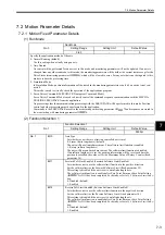
7.2.1 Motion Fixed Parameter Details
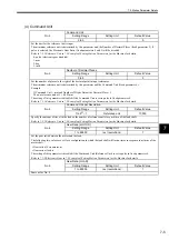
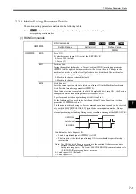
(1) Run Mode
(2) Function Selection 1
No. 0
Run Mode
Setting Range
Setting Unit
Default Value
0 to 3
−
0
Specify the application method of the axis.
0: Normal Running (default)
Use this setting when actually using an axis.
1: Axis Unused
No control will be performed for an axis set to this mode, and monitoring parameters will not be updated. If an axis is
changed from any other run mode to this mode, the monitoring parameters will be held at the current status except for the
Drive Status (monitoring parameter IW
00), which will be cleared to zeros. Set any axis that is not being used to this
mode to reduce the processing time.
2: Simulation Mode
In Simulation Mode, position information will be stored in the monitoring parameters even if a Servodrive is not con-
nected.
This mode is used to virtually check the operation of the applications program.
3: Servo Driver Command (SERVOPACK Transparent Command Mode)
Servo Driver Command Mode is used to directly control the command-response communication with the MECHA-
TROLINK SERVOPACK from the application.
No processing other than communication processing with the SERVOPACK will be performed in this mode. Position
control and other processing must be performed in the application.
Commands to the SERVOPACK are set in the area starting with setting parameter OW
70 and responses are stored in
the area starting with monitoring parameter IW
70.
No. 1
Function Selection 1
Setting Range
Setting Unit
Default Value
−
−
0000H
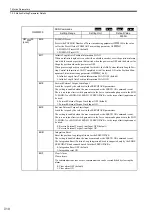
No. 1
Bit 0
Axis Type
Set whether or not there is a limit on controlled axis travel.
0: Linear (finite length axis) (default)
The axis will have limited movement. The software limit function is enabled.
1: Rotary (infinite length axis)
The axis will have unlimited movement. The software limit function is disabled.
If an infinite length axis is set, the position information will be reset each time the
position is exceeded the value set for the Maximum Value of Rotary Counter (fixed
parameter 10).
Bit 1
Forward Soft Limit Enabled (Forward Software Limit Enabled)
Set whether or not to use the software limit function in the positive direction.
Set the software limit as the Forward Software Limit (fixed parameter 12).
This setting is disabled if the axis is set to an infinite length axis.
The software limit function is enabled after Zero Point Return or Zero Point Setting
(IB
0C5 is ON) has been completed. For details, refer to
14.3 Software Limit Func-
tion
.
0: Disabled (default)
1: Enabled
Bit 2
Reverse Soft Limit Enabled (Reverse Software Limit Enabled)
Set whether or not to use the software limit function in the negative direction.
Set the software limit as the Reverse Software Limit (fixed parameter 14).
This setting is disabled if the axis is set to an infinite length axis.
The software limit function is enabled after Zero Point Return or Zero Point Setting
(IB
0C5 is ON) has been completed. For details, refer to
14.3 Software Limit Func-
tion
.
0: Disabled (default)
1: Enabled

