
APPENDIX B: ELECTRICAL AND DATA CONNECTIONS
HF25D DC RESISTANCE WELDING SYSTEM
990-333
B-3
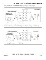
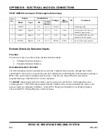
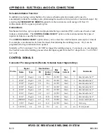
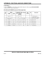
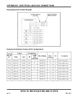
The bulkhead connectors that receive the six removable terminal block plugs are connectors J1, J2 and
J3 on the control board. The terminal block plug to control board connector pin relationship is as
follows:
J1
Pins 1-10
J1
Pins 11-20
J2
Pins 1-10
J2
Pins 11-20
J3
Pins 1-10
J3
Pins 11-20
TB1
Pins 1-10
TB2
Pins 11-20
TB3
Pins 21-30
TB4
Pins 31-40
TB5
Pins 41-50
TB6
Pins 51-60
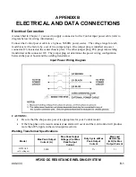
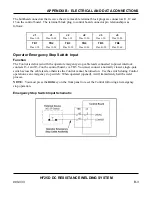
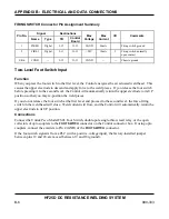
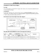
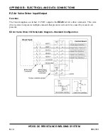
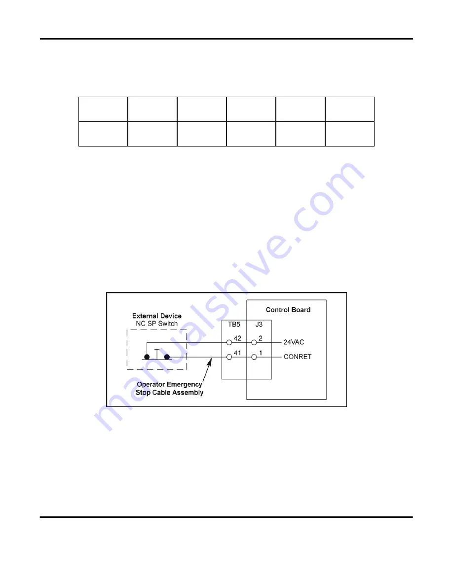
Operator Emergency Stop Switch Input
Function
The Control is delivered with the operator emergency stop cable leads connected to power interlock
contacts J3-1 and J3-2 on the control board, via TB5. You must connect a normally closed, single-pole
switch across the cable leads, otherwise the Control cannot be turned on. Use the switch during Control
operation as an emergency stop switch. When operated (opened), it will immediately halt the weld
process.
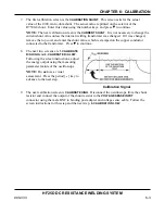
NOTE:
You must press the
RUN
key on the front panel to reset the Control following an emergency
stop operation.
Emergency Stop Switch Input Schematic
Содержание HF25A
Страница 9: ...HF25D DC RESISTANCE WELDING SYSTEM 990 333 ix ...
Страница 10: ......
Страница 20: ......
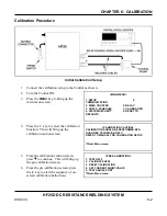
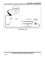
Страница 84: ...CHAPTER 6 CALIBRATION HF25D DC RESISTANCE WELDING SYSTEM 990 333 6 4 Final Calibration Setup ...
Страница 113: ......
Страница 129: ......
Страница 153: ......
Страница 171: ......


