CHAPTER 5. MAINTENANCE
HF25D DC RESISTANCE WELDING SYSTEM
5-4
990-333
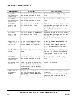
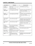
Alarm Message
Description
Corrective Action
CURRENT 1
GREATER THAN
UPPER LIMIT
Actual weld current is greater than the
user set Upper Limit value for Weld1.
Reset the Upper Limit for Weld1 to a larger
value.
CURRENT 2
GREATER THAN
UPPER LIMIT
Actual weld current is greater than the
user set Upper Limit value for Weld2.
Reset the Upper Limit for Weld2 to a larger
value.
CURRENT 1
LOWER THAN
LOWER LIMIT
Actual weld current is less than the user
set Lower Limit value for Weld1.
Weld splash can cause the actual weld current to
drop below the user set Lower Limit for Weld1.
Add upslope to reduce weld splash.
Reset the lower Limit for Weld1 to a smaller
value.
CURRENT 2
LOWER THAN
LOWER LIMIT
Actual weld current is less than the user
set Lower Limit value for Weld2.
Weld splash can cause the actual weld current to
drop below the user set Lower Limit for Weld2.
Add upslope to reduce weld splash.
Reset the lower Limit for Weld2 to a smaller
value.
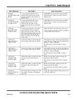
EMERGENCY STOP
- OPERATOR
ACTIVATED
The Operator Emergency Stop switch
has been activated. All power to the
HF25/26 is immediately terminated.
Remove any unsafe operating conditions at the
welding electrodes.
Reset the Operator Emergency Stop switch.
Turn off power to the HF25/26, then turn it on
again
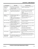
CHECK VOLTAGE
CABLE
No electrode voltage measurement was
made.
Verity that the Voltage Sense Cable is properly
connected to the electrodes or electrode holder.
NOTE:
Polarity is not important for the cable
connection.
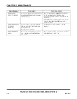
CURRENT 1
GREATER THAN
UPPER LIMIT
Actual weld current is greater than the
user set Upper Limit value for Weld1.
Reset the Upper Limit for Weld1 to a larger
value.
ENERGY SETTING
TOO SMALL
While in the voltage or power feedback
mode, the HF25/26 could not control the
energy setting because the required
current was smaller than the minimum
current specified.
Increase the energy setting.
FIRING SWITCH
BEFORE FOOT
SWITCH
The Firing Switch input has been
activated before the Foot Switch has
been activated, preventing weld current
from flowing.
Check the weld head for an improperly adjusted
firing switch.
Automation Only - Check the timing on the PLC
control lines to the Firing Switch and Foot
Switch inputs.
Содержание HF25A
Страница 9: ...HF25D DC RESISTANCE WELDING SYSTEM 990 333 ix ...
Страница 10: ......
Страница 20: ......
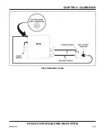
Страница 84: ...CHAPTER 6 CALIBRATION HF25D DC RESISTANCE WELDING SYSTEM 990 333 6 4 Final Calibration Setup ...
Страница 113: ......
Страница 129: ......
Страница 153: ......
Страница 171: ......

