APPENDIX B: ELECTRICAL AND DATA CONNECTIONS
HF25D DC RESISTANCE WELDING SYSTEM
B-6
990-333
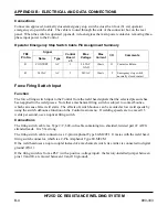
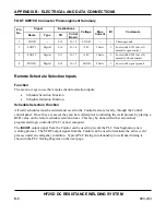
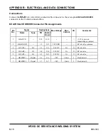
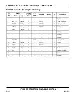
FIRING SWITCH Connector Pin Assignment Summary
Signal Destinations
Pin No.
Name Type TB Control
Board
Max
Voltage
Max
Current
I/O
Comments
1
FIREG
Digital
2-12
J1-12
SGND
20mA
Firing switch ground
2
FIRE1
Digital
2-11
J1-11
+24V
10mA
I
Firing switch normally
open contact
Shld CGND -- 2-15 J1-15 CGND --
-- Chassis
ground
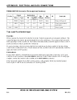
Two-Level Foot Switch Input
Function
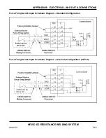
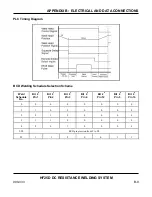
When you press the foot switch to the first level, the Control energizes the air actuated weld head. This
causes the upper electrode to descend and apply force to the weld pieces. If you release the foot switch
before pressing it to the second level, the Control will automatically return the upper electrode to its UP
position so that you may re-position the weld pieces.
If you do not release the foot switch at the first level and proceed to the second level, the force-firing
switch in the weld head will close. Weld current will flow, and the Control will automatically return the
upper electrode to its UP position.
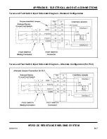
Connections
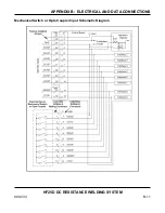
Connect the Unitek Peco Model FS2L Foot Switch, double-pole single-throw reed relay, or the open
collectors of opto couplers to the
FOOT SWITCH
connector on the Control connector box. If using opto
couplers, connect the emitters to Pin 4 (GND) of the
FOOT SWITCH
connector.
If the foot switch signal is from a PLC (with a positive-voltage input), the factory-installed jumper
between pins 19 and 20, are moved between 19 and 18 (ground).
Содержание HF25A
Страница 9: ...HF25D DC RESISTANCE WELDING SYSTEM 990 333 ix ...
Страница 10: ......
Страница 20: ......
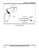
Страница 84: ...CHAPTER 6 CALIBRATION HF25D DC RESISTANCE WELDING SYSTEM 990 333 6 4 Final Calibration Setup ...
Страница 113: ......
Страница 129: ......
Страница 153: ......
Страница 171: ......

