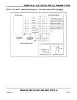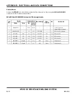
APPENDIX B: ELECTRICAL AND DATA CONNECTIONS
HF25D DC RESISTANCE WELDING SYSTEM
990-333
B-17
Relay Outputs
Function
Four mechanical relays on the control board can be independently programmed to supply alarm or weld
status contact signal outputs. You can access the programming function through the main menu, as
described in
Chapter 3
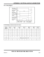
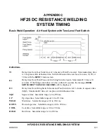
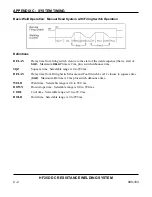
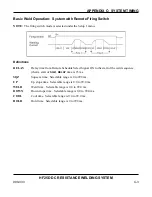
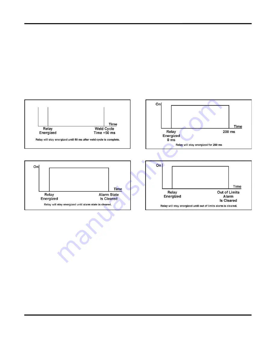
. The events that you can program for each relay and their timing diagrams are as
follows:
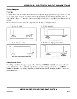
Relay contacts closed or open in the energized state. Relays are energized when:
1. Weld cycle starts.
2. Weld cycle ends.
3. Alarm state is detected.
4. Weld is out of programmed limits.
Relay Connections
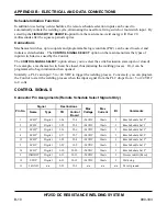
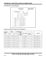
The Relay 1 and Relay 2 outputs are available at the 15-pin
CONTROL SIGNALS
connector on the rear
panel of the Control. Contact Unitek Miyachi if you need the mating connector for the
CONTROL
SIGNALS
connector. The Relay 3 and Relay 4 outputs are available at bulkhead connector TB4 inside
the connector box.
Содержание HF25A
Страница 9: ...HF25D DC RESISTANCE WELDING SYSTEM 990 333 ix ...
Страница 10: ......
Страница 20: ......
Страница 84: ...CHAPTER 6 CALIBRATION HF25D DC RESISTANCE WELDING SYSTEM 990 333 6 4 Final Calibration Setup ...
Страница 113: ......
Страница 129: ......
Страница 153: ......
Страница 171: ......

