CHAPTER 1: DESCRIPTION
HF25D DC RESISTANCE WELDING SYSTEM
1-2
990-333
•
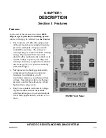
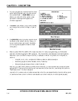
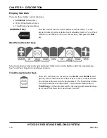
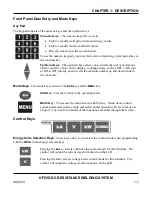
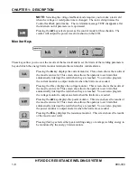
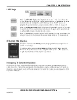
You can program the Control from the front
panel, using simplified key clusters and on-
screen data fields. A
MAIN MENU
screen
allows you select all of the system setup
options for working with inputs from
external equipment.
<MAIN MENU>
1.
SETUP
5.
COMMUNICATION
2. WELD COUNTER
6. RELAY
3. COPY A SCHEDULE
7. CALIBRATION
4. SYSTEM SECURITY
8. RESET TO
DEFAULTS
NUMBER Select an item
•
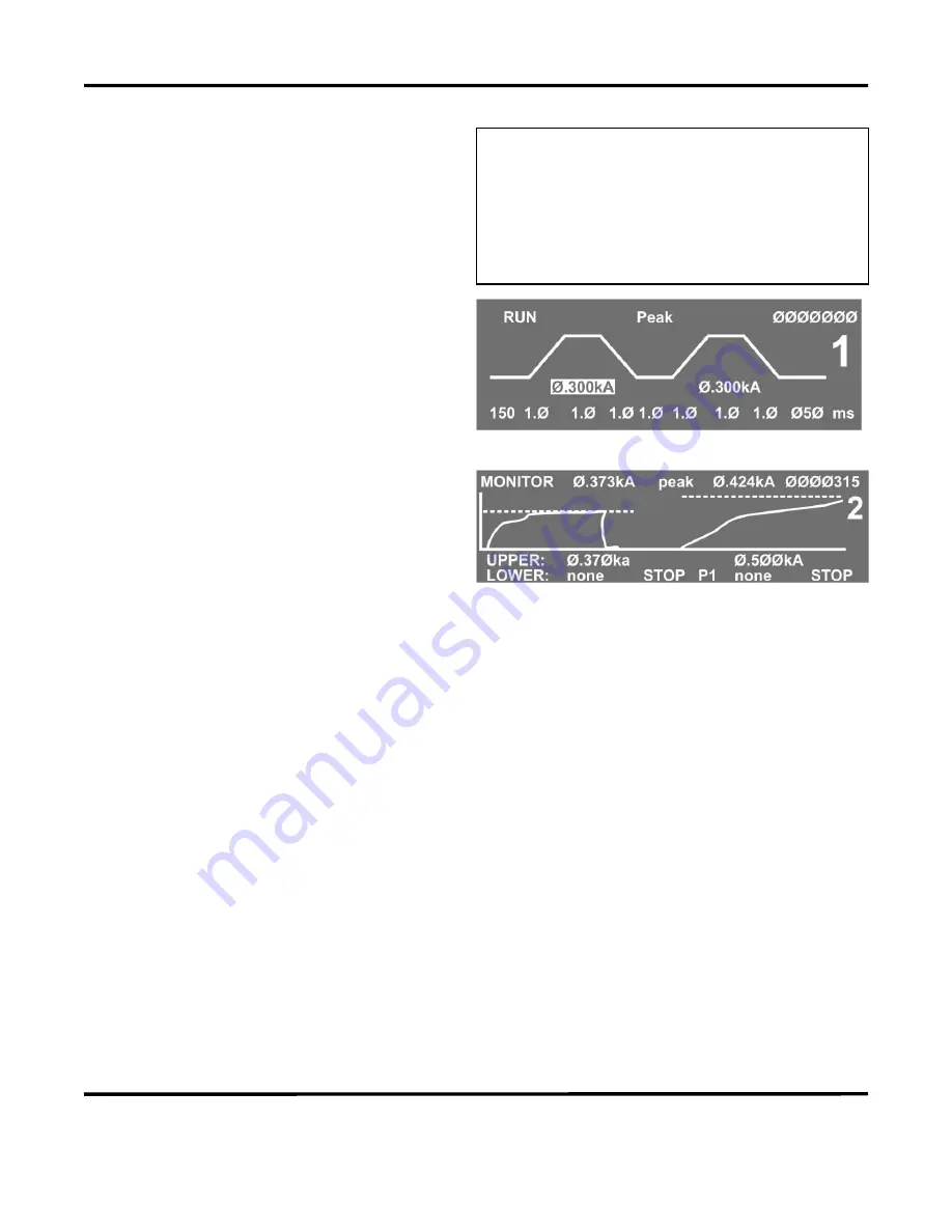
The
RUN
screen allows you to easily modify
any time period, current, voltage, or power
value.
Run Screen
•
The
MONITOR
screen provides instant visual
feedback on the actual current, voltage, or
power used to make each weld. It permits
you to program adjustable limits for both
weld pulses.
Monitor Screen
•
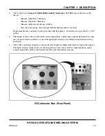
Rear-mounted RS-232 and RS-485 connectors allow for remote programming, weld schedule
selection, and data logging for SPC purposes. The Control has communication and data options
that allows you to connect a single Control, or multiple Controls, to a printer or a computer in
order to:
−
Compile, store, view, and print weld history data for detailed analysis.
−
Remotely program weld schedules on the Control(s).
−
Remotely program menu items on the Control(s).
However, to enable the Control to perform these functions, you must install the software from the
optional
HF25 Advanced Serial Datacom Communications Interface Kit
, commonly referred to as
"the Datacom kit," in a host computer.
Appendix E, Communications
in this manual lists all of the commands that the Control will respond
to, and instructions on how to format commands sent to the Control so it will respond properly.
Содержание HF25A
Страница 9: ...HF25D DC RESISTANCE WELDING SYSTEM 990 333 ix ...
Страница 10: ......
Страница 20: ......
Страница 84: ...CHAPTER 6 CALIBRATION HF25D DC RESISTANCE WELDING SYSTEM 990 333 6 4 Final Calibration Setup ...
Страница 113: ......
Страница 129: ......
Страница 153: ......
Страница 171: ......


