


CHAPTER 3: USING PROGRAMMING FUNCTIONS
HF25 DC RESISTANCE WELDING SYSTEM
3-30
990-333
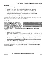
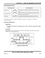
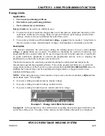
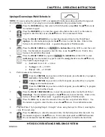
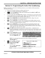
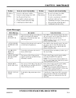
In this case, the operator has selected the option to terminate the weld energy under this condition,
so the energy limits monitor terminates the Pulse 1 weld and inhibits the Pulse 2 weld if it had been
programmed.
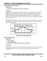
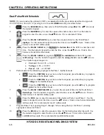
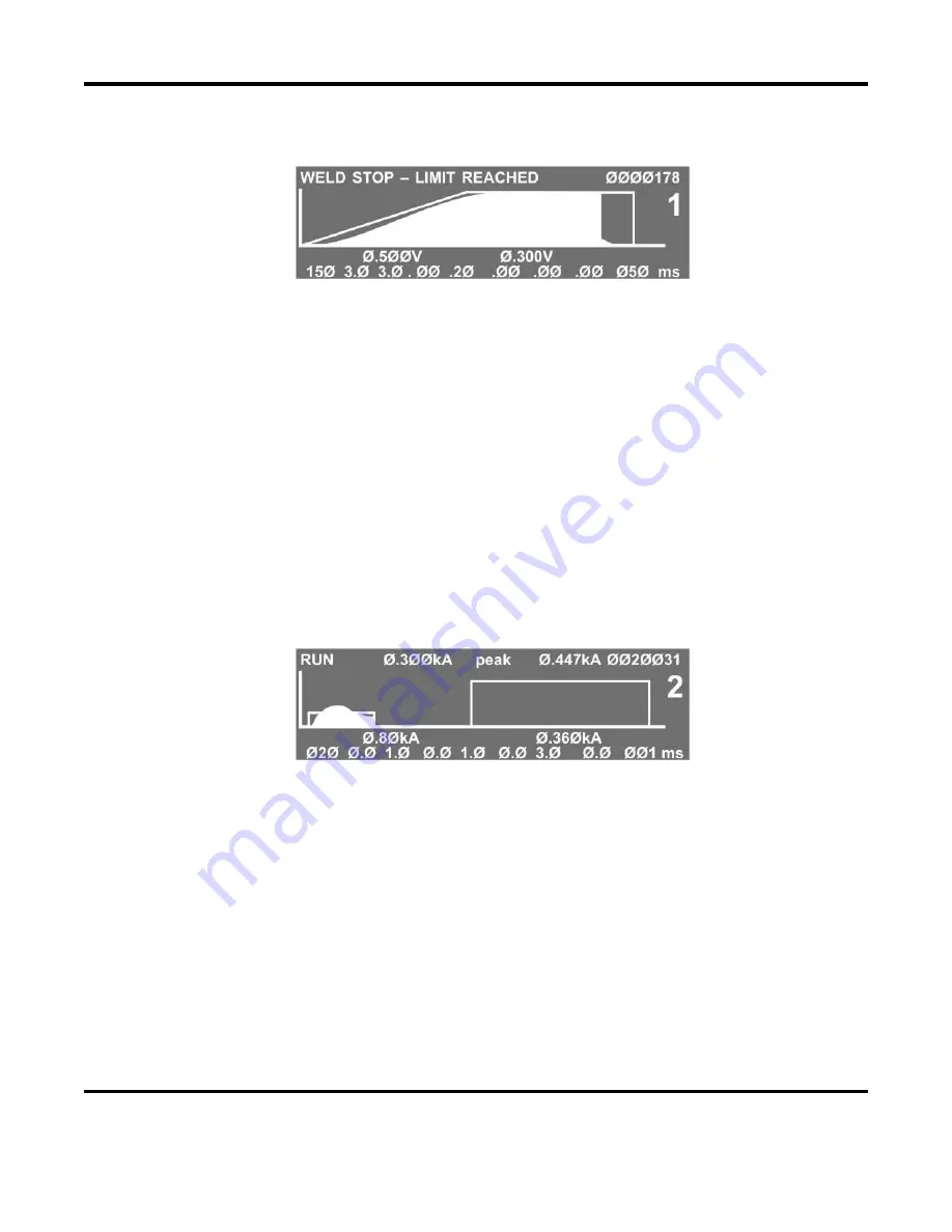
Example 2: Sufficient Current Level
Example #2
: In the profile above, the weld current limit is at a sufficient level to get a good weld.
Pre-Weld Check
Application
•
Detect Misaligned or Missing parts.
Function
This is used to see if parts are misaligned or missing
before
a welding pulse is delivered to the weld
head. If a part is missing or misaligned, you do
not
want the machine to weld because the result
would be an unacceptable weld and/or damaged electrodes.
Pre-Weld Check
is similar to
Energy Limits
, however in this case Pulse 1 should be very
short
(1-2 milliseconds), and the current should be
low
, about 10% of the Pulse 2 current. Pulse 1 should
be used as a measurement pulse and should
not
perform a weld.
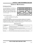
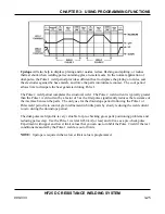
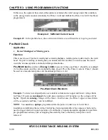
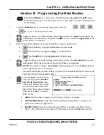
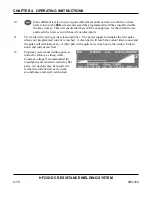
Pre-Weld Check Waveform
Example
: To detect misaligned parts, use constant current and set upper and lower voltage limits
for Pulse 1 If parts are
misaligned
, the work piece resistance will be higher, so the voltage will be
higher. If parts are
missing
, voltage will be lower. In either case, the Pulse 1 upper or lower limits
will be exceeded, and Pulse 1 can be inhibited.
NOTE:
You
must
have
upslope
programmed into the pulse in order to set a lower limit.
In addition to inhibiting the weld, the Control has four programmable relay outputs, which can be
used to trigger alarms to signal operators of weld faults or signal automation equipment to perform
pre-programmed actions, such as stopping the assembly line so the faulty weld piece can be
removed.
Содержание HF25A
Страница 9: ...HF25D DC RESISTANCE WELDING SYSTEM 990 333 ix ...
Страница 10: ......
Страница 20: ......
Страница 84: ...CHAPTER 6 CALIBRATION HF25D DC RESISTANCE WELDING SYSTEM 990 333 6 4 Final Calibration Setup ...
Страница 113: ......
Страница 129: ......
Страница 153: ......
Страница 171: ......


