HF25D DC RESISTANCE WELDING SYSTEM
990-333
6-1
CHAPTER 6
CALIBRATION
Calibration
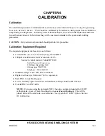
The calibration procedure is initiated at the main menu, as described in
Chapter 3, Using Programming
Functions, Section I, Menus. .
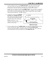
The Control is calibrated by the software, using inputs from a calibration
setup during a weld process. Following a few calibration inputs, the Control will adjust itself and store
the calibration values in RAM, where they will be used as standards for the operational welding
parameters.
CAUTION:
Only authorized personnel should perform this procedure.
Calibration Equipment Required
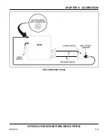
The required equipment for the setup is as follows:
•
2 weld cables, No. 2/0, 1 ft (30 cm) long, PN 2/0 BB11
•
1000µ
Ω
coaxial shunt resistor accurate to ±0.2%.
Source for shunt resistor: Model R7500-8
T & M Research Products, Inc.
139 Rhode Island Street NE
Albuquerque,
NM
87108
Telephone: (505) 268-0316
•
Shielded voltage sense cable, PN 4-32998-01
•
Digital oscilloscope, Tektronix 724C or equivalent
•
Male BNC to dual binding post
•
2-wire, normally open switch for weld initiation, mating connector PN 520-011
•
Coaxial BNC-to-BNC cable
NOTE:
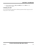
If you are using the optional LVDT, the only equipment required for LVDT
calibration is a piece of metal machined to an
exact known thickness
. This will be
placed between the electrodes as a reference. See
Appendix D, LVDT Option, Section
III, Calibration.
Содержание HF25A
Страница 9: ...HF25D DC RESISTANCE WELDING SYSTEM 990 333 ix ...
Страница 10: ......
Страница 20: ......
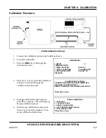
Страница 84: ...CHAPTER 6 CALIBRATION HF25D DC RESISTANCE WELDING SYSTEM 990 333 6 4 Final Calibration Setup ...
Страница 113: ......
Страница 129: ......
Страница 153: ......
Страница 171: ......

