


CHAPTER 3: USING PROGRAMMING FUNCTIONS
HF25 DC RESISTANCE WELDING SYSTEM
990-333
3-17
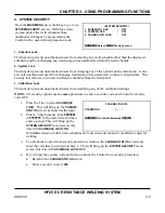
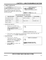
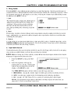
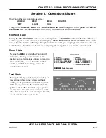
Weld State
Once weld current is flowing, the Control is in the
WELD
state. You can terminate weld current in five
ways:
•
Remove the first level of a single-level foot switch, assuming weld abort is ON.
•
Remove the second-level of a two-level foot switch, assuming weld abort is ON.
•
Input the process stop signal (refer to
Appendix B, Electrical and Data Connections
).
•
Open the normally closed switch across the operator emergency stop switch cable.
NOTE:
This action removes all power from the Control.
•
Through the action of the monitor settings.
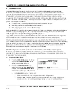
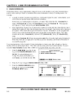
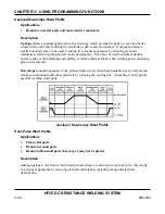
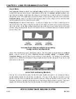
Completion of the firing state is indicated by a profile of actual delivered weld energy superimposed on
the programmed weld energy trace, as shown in the example above.
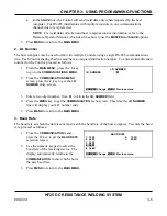
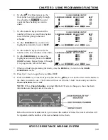
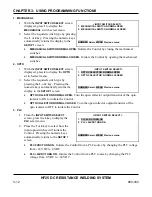
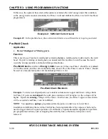
Monitor State
From the
MONITOR
keys section on the front
panel, press the
kA
,
V
,
kW
or
Ω
key to go to the
monitor state. In this state, when the Control
detects an out of limits condition, it will take one
of four actions, depending on the selection made
with the
MONITOR
display, as shown at the right.
Also, an alarm message will be displayed and any relay set for
ALARM
or OUT OF LIMITS
will be
energized.
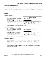
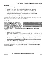
The selections are:
•
NONE:
The weld cycle will continue.
•
STOP DURING PULSE 1:
The weld cycle will stop immediately. Pulse 2 (if applicable) will not
fire.
•
INHIBIT 2ND PULSE:
During the
COOL
time, the Control calculates the average of the Weld1
pulse (including upslope, weld and downslope). If the average of the Weld1 pulse is out of
limits, the weld cycle will stop and the Weld2 pulse will be inhibited.
•
APC: STOP PULSE 1/ALLOW PULSE 2
stops Pulse 1 immediately after upper or lower energy
limits are exceeded, but allows Pulse 2 to fire.
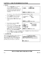
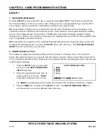
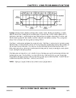
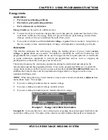
The display shows the actual trace of the weld current, voltage or power, and either the peak or the
average value for each weld pulse as selected by pressing the
PEAK/AVERAGE
key.
See
Section IV, Using HF28 Welding and Monitoring Functions
for a detailed description of energy
limits monitor operation.
Содержание HF25A
Страница 9: ...HF25D DC RESISTANCE WELDING SYSTEM 990 333 ix ...
Страница 10: ......
Страница 20: ......
Страница 84: ...CHAPTER 6 CALIBRATION HF25D DC RESISTANCE WELDING SYSTEM 990 333 6 4 Final Calibration Setup ...
Страница 113: ......
Страница 129: ......
Страница 153: ......
Страница 171: ......


