APPENDIX A: TECHNICAL SPECIFICATIONS
HF25D DC RESISTANCE WELDING SYSTEM
990-333
A-3
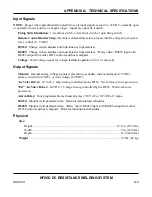
Input Signals
NOTE:
Except where parenthetically noted below, all input signals accept 5 to 24 VDC, normally open
or normally closed, positive or negative logic. Inputs are optically isolated.
Firing Switch Initiation:
1-level foot switch, 2-level foot switch or opto firing switch.
Remote Control Barrier Strip:
Remote weld schedule select, process inhibit, emergency stop and
force control (0 - 5 VDC).
RS232:
Change weld schedules and individual weld parameters.
RS485:
Change weld schedules and individual weld parameters. “Daisy chain” RS485 input with
RS485 output from other HF25 controls and host computer.
Voltage:
Weld voltage signal for voltage feedback operation (0 to 10 volt peak).
Output Signals
Monitor:
Internal analog voltage signals representing secondary current feedback (0-5 VDC),
primary current (0-4 VDC), or weld voltage (0-5VDC).
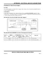
Air Valve Driver:
24 VAC, 1 amp; timing controlled by the HF25. No weld over-force protection.
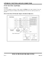
“EZ” Air Valve Driver:
24 VDC, 1.5 amps: timing controlled by the HF25. Weld over-force
protection.
Alarm Relay:
Four programmable mechanical relays: 250 VAC or 30 VDC at 5 amps
.
RS232:
Monitor weld parameter data. Download and upload schedules.
RS485:
Monitor weld parameter data. “Daisy chain” RS485 input with RS485 output from other
HF25 Controls and host computer. Download and upload schedules.
Physical
Size:
Height .................................................................................................................12.8
in. (325 mm)
Width .......................................................................................................................9 in. (230 mm)
Depth .......................................................................................................................18.0 (460 mm)
Weight
.......................................................................................................................... 62 lbs. (28 kg)
Содержание HF25A
Страница 9: ...HF25D DC RESISTANCE WELDING SYSTEM 990 333 ix ...
Страница 10: ......
Страница 20: ......
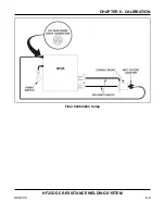
Страница 84: ...CHAPTER 6 CALIBRATION HF25D DC RESISTANCE WELDING SYSTEM 990 333 6 4 Final Calibration Setup ...
Страница 113: ......
Страница 129: ......
Страница 153: ......
Страница 171: ......

