CHAPTER 2: INSTALLATION AND SETUP
HF25D DC RESISTANCE WELDING SYSTEM
990-333
2-5
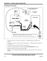
6.
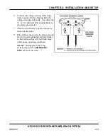
Connect the voltage sensing cable clips
that are packed in the shipping kit to the
voltage sensing cable leads. Use either the
¼” or 1/8” diameter clip, as appropriate to
the electrode diameter.
7.
Attach a clip directly to each electrode as
shown on the right.
8.
Put a strain relieve on each voltage sensing
lead to its corresponding electrode holder
so that the lead clips will not break away
under heavy operating conditions.
NOTE
:
Do
not
attach the firing
switch, foot switch or
EMERGENCY
STOP
cables at this time.
Содержание HF25A
Страница 9: ...HF25D DC RESISTANCE WELDING SYSTEM 990 333 ix ...
Страница 10: ......
Страница 20: ......
Страница 84: ...CHAPTER 6 CALIBRATION HF25D DC RESISTANCE WELDING SYSTEM 990 333 6 4 Final Calibration Setup ...
Страница 113: ......
Страница 129: ......
Страница 153: ......
Страница 171: ......

