INDEX
HF25D DC RESISTANCE WELDING SYSTEM
990-333
Index-5
S
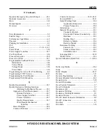
Schedule Lock ......................................................3-3
Schedule Selector Key ..........................................1-6
Screening DOE’s ...............................................D-10
Scrolling Through Fields on the Screen ............D-10
Select a Weld Schedule ........................................4-3
Selection Scheme .................................................B-9
Set New Electrodes to “Zero” ...........................D-10
Setup
.......................................................2-3
Air-Actuated Weld Head Connection .............2-7
Connections to External Equipment ................2-3
Foot Pedal-Actuated Weld Head Connection .2-6
Weld Head Connections ..................................2-4
Setup 1
........................................................3-10
Setup 2
........................................................3-13
Shipping Kit Contents .........................................A-4
Single-Pulse Weld Profile ..................................3-21
Single-Pulse Weld Schedule .................................4-4
Size
......................................................A-3
Solder or Braze Joint ...........................................D-2
Solid-State Joint ..................................................D-2
Space Requirements .............................................2-1
Standard Air Valve Driver Output ....................B-13
Stop Energy At:
(Weld to a Specific Displacement) ............D-13
Single-Pulse Weld Profile ..................................3-23
Switch Debounce Time ......................................3-10
System Lock .........................................................3-3
System Security ....................................................3-3
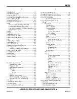
System Timing ....................................................C-1
T
Technical Specifications ......................................A-1
Optional
Accessories
...................................A-4
Output
Signals
.............................................A-3
Performance
Capabilities
.............................A-2
Physical
......................................................A-3
Size
......................................................A-3
Weight
..................................................A-3
Power
......................................................A-1
Shipping
Kit
Contents
.................................A-4
Weld Energy Limits Monitoring .................A-2
Weld Head System Compatibility ...............A-2
Test State ........................................................3-15
Time/Energy Selector Keys ..................................1-6
Troubleshooting ....................................................5-2
Two-Level Foot Switch Input .............................B-6
U
Update Graph After Weld .................................. 3-14
Upslope/Downslope Weld Profile ..................... 3-24
Upslope/Downslope Weld Schedule ................... 4-5
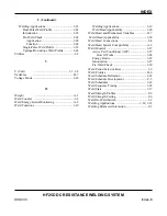
Using HF25 Welding
and
Monitoring
Functions
.................. 3-19
Using Programming Functions ............................ 3-1
Menus
......................................................... 3-1
Main
Menu
................................................ 3-1
Calibration............................................. 3-6
Chain
Schedules
................................... 3-8
Communication
.................................... 3-4
Baud
Rate......................................... 3-5
Communication
Role
...................... 3-4
I.D.
Number
.................................... 3-5
Copy
A
Schedule
................................. 3-2
Relay
.................................................... 3-6
Reset
To
Defaults
................................. 3-7
Reset
All
Schedules
........................ 3-7
Reset
System
Parameters
................ 3-7
Setup
.................................................... 3-1
System
Security
................................... 3-3
Calibration
Lock
............................. 3-3
Schedule
Lock
................................ 3-3
System
Lock
................................... 3-3
Weld
Counter
....................................... 3-2
Overview
................................................... 3-1
Setup
1
..................................................... 3-10
Control Signals Select ................... 3-13
Firing Switch ................................ 3-11
Auto
.............................................. 3-11
None
.............................................. 3-11
Remote
.......................................... 3-11
Footswitch Weld Abort ................. 3-10
Input Switch Select ....................... 3-11
Mechanical
.................................... 3-12
OPTO
............................................ 3-12
PLC
............................................... 3-12
Switch Debounce Time ................. 3-10
Setup
2
..................................................... 3-13
Buzzer
Loudness
................................ 3-13
Display
Contrast
................................. 3-13
End
Of
Cycle
Buzzer
......................... 3-13
Update
Graph
After
Weld
.................. 3-14
Using Weld and Monitor Functions .................. 3-21
Overview
...................................................... 3-21
Weld Schedule Definition ............................ 3-22
Weld Sequence Timing ................................ 3-22
Содержание HF25A
Страница 9: ...HF25D DC RESISTANCE WELDING SYSTEM 990 333 ix ...
Страница 10: ......
Страница 20: ......
Страница 84: ...CHAPTER 6 CALIBRATION HF25D DC RESISTANCE WELDING SYSTEM 990 333 6 4 Final Calibration Setup ...
Страница 113: ......
Страница 129: ......
Страница 153: ......
Страница 171: ......

