HF25D DC RESISTANCE WELDING SYSTEM
990-333
Index-1
INDEX
A
Accessing Setup 2 ................................................3-4
Active Part Conditioner (APC) ..........................3-25
Adjusting Monitor Limits ...................................4-11
Air-Actuated Weld Head Connection ...................2-7
Alarm Messages ........................................... 5-1, 5-3
Alarm State .....................................................3-16
Application .........................3-24, 3-25, 3-27, 3-28
Application Perspective .......................................D-8
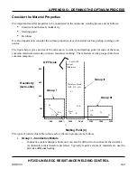
Approach to Weld Development .........................D-7
B
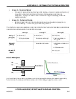
Basic Principles ...................................................D-4
Basics of Resistance Welding .............................C-1
Electrode
Maintenance
................................C-5
Electrode
Selection
......................................C-2
Interaction of Welding Parameters ..............C-6
Resistance Welding Parameters ...................C-1
Weld Schedule Development ......................C-5
Weld Strength Profiles .................................C-6
Weld Strength Testing .................................C-6
Welding Parameter Interaction ....................C-1
Baud Rate
.......................................................3-5
BCD Welding Schedule Selection Scheme .........B-9
Before You Start .......................................... 4-1, D-4
Buzzer Loudness ................................................3-13
C
Calibration
............................................... 3-6, 6-1
Calibrating the LVDT .....................................6-4
Calibration
.......................................................6-1
Calibration Equipment Required .....................6-1
Calibration Procedure ....................................
6-2
Calibration Lock ...................................................3-3
Chain Schedules ...................................................3-8
Changing from Inches to Millimeters (MM) .....D-10
Command Format ................................................ E-4
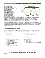
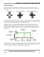
Common Problems ..............................................D-9
Communication ....................................................3-4
Communication Role ............................................3-4
Communications .................................................. E-1
Command
Format
........................................ E-4
Computer
Originated
Commands
........ E-5
Control
Originated
Commands
.......... E-15
Communications
Protocol
and
Commands
...........................................E-4
Host
settings
.................................................E-2
Overview
......................................................E-1
Remote
Programming
..................................E-1
RS-232 Serial Connector Information .........E-2
RS-485
Connectors
......................................E-1
Communications Protocol and Commands .........E-4
Compressed Air ................................................... 4-2
Compressed Air and Cooling Water .................... 2-2
Computer Originated Commands ........................E-5
Conductive Metals .............................................. D-3
Conductivity ...................................................... D-3
Connections
............................................... 4-2
Connections to External Equipment .................... 2-3
Control Keys ....................................................... 1-7
Control Originated Commands ..........................E-15
Control Signals ..................................................B-10
Control Signals Select ....................................... 3-13
Copy a Schedule ................................................... 3-2
Criteria for Success ................................. D-10, D-11
Current Mode ..................................................... 3-26
D
Description ....................................................... 1-1
Displacement .................................................... D-12
Display Contrast ................................................ 3-13
Display Controls .................................................. 1-6
Display
....................................................... 1-5
Distance
....................................................... 1-9
Dual-Pulse Weld Profile .................................... 3-24
Dual-Pulse Weld Schedule .................................. 4-6
E
Electrical And Data Connections .........................B-1
BCD Welding Schedule
Selection
Scheme
.................................B-9
Control
Signals
..........................................B-10
Electrical
Connection
...................................B-1
EZ Air Valve Driver Input/Output .............B-14
Force Firing Switch Input ............................B-4
I/O Signal Interface General Description ....B-2
Monitor
Output
..........................................B-19
Содержание HF25A
Страница 9: ...HF25D DC RESISTANCE WELDING SYSTEM 990 333 ix ...
Страница 10: ......
Страница 20: ......
Страница 84: ...CHAPTER 6 CALIBRATION HF25D DC RESISTANCE WELDING SYSTEM 990 333 6 4 Final Calibration Setup ...
Страница 113: ......
Страница 129: ......
Страница 153: ......
Страница 171: ......

