


APPENDIX D: LVDT OPTION
HF25 DC RESISTANCE WELDING SYSTEM
990-333
D-3
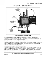
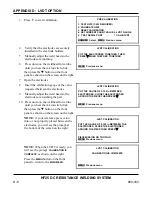
Section II. LVDT Adjustment
LVDT Installed on Typical Weld Head
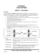
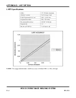
The LVDT is most accurate in the
middle
of its one-inch stroke. Therefore, best measurement
performance is achieved by adjusting the LVDT so that welding occurs in the middle of its stroke. The
following instructions apply to the LVDT in the 80 DSPK:
If Total Electrode Stroke Is
LESS
Than 0.5-inch:
Loosen the adjusting screws and move the LVDT up or down so that when the electrodes are closed, the
LVDT is extended approximately
3/4 inch
.
This will place it in the middle of its stroke. When the
position is correct, tighten the Adjusting Screws.
If Total Electrode Stroke Is
GREATER
than 0.5-inch
Loosen the adjusting screws and move the LVDT up or down so that when the electrodes are open, the
LVDT is at its
minimum
stroke (fully compressed). This will put the welding position as close to the
middle of the LVDT stroke as possible. When the position is correct, tighten the Adjusting Screws.
The 60 series head with LVDT comes pre-adjusted from the factory and should not require adjustment.
Содержание HF25A
Страница 9: ...HF25D DC RESISTANCE WELDING SYSTEM 990 333 ix ...
Страница 10: ......
Страница 20: ......
Страница 84: ...CHAPTER 6 CALIBRATION HF25D DC RESISTANCE WELDING SYSTEM 990 333 6 4 Final Calibration Setup ...
Страница 113: ......
Страница 129: ......
Страница 153: ......
Страница 171: ......


