background image

Hardware Installation

Commander i+ Product Service Manual - Issue 2

Page 3-27


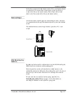
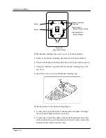
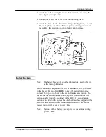
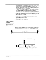
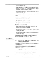
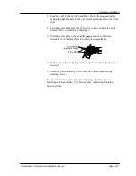
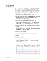
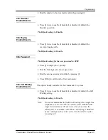
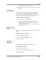
Feed the cable from the AFU and the cable to the external paging
system through the hole in the rear cover and mount the cover to the
wall.


Terminate the cable from the AFU to the outside terminals of the
terminal block - polarity is unimportant.


Terminate the cable to the external paging system to the inner
terminals of the terminal block - polarity is unimportant.


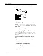
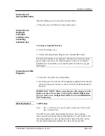
Make a test external paging call and adjust the output level pot as
required.


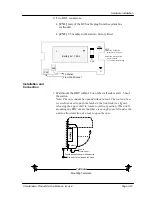
Attach the front assembly to the rear cover and replace the top
retaining screw.


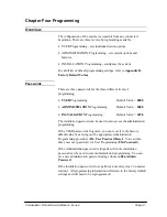
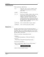
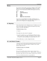
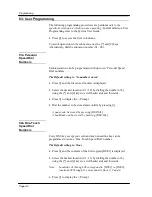
To programme the system for external paging operation refer to
Installation Programming - 13i Devices (Fax, Answering Machine,
Door Station).

To external

paging system

From AFU

Содержание Commander i

Страница 1: ...Telstra Commander i Product Service Manual Commander i and Commander i incorporating Installation and Maintenance Manual Serial Item 749 028 Issue 2 ...

Страница 2: ...chnical training This document now replaces the Commander i System Installation manual issue 1 All copies of issue 1 documentation should be replaced and securely destroyed Scope of Document The document includes all reference and support information to facilitate the installation and assurance of the Commander i digital keysystems and peripheral equipment The documentation also includes informati...

Страница 3: ...l details When completed mail your comments to Telstra Commander Remote Access Centre Locked Bag 1634 Adelaide SA 5800 or Fax the details to 1800 044 113 Name Designation Region Operations Group Business and Government Commercial SDU Address Postcode Telephone Fax Manual Commander i Product Service Manual Issue 2 Suggestions ...

Страница 4: ...ine a Technical Helpline and a Product Development Team to monitor both current and future products Apart from being a fault reporting centre the TCRAC offers a range of value added services for both internal and external customers It is chartered to clear 70 percent of customer calls at first point of contact with the centre effectively reducing site visits and response times while increasing cus...

Страница 5: ...lstra technical staff and its customers by providing highly focussed and cost effective Commander CPE support By contributing towards reducing Telstra s product unit costs on CPE it is helping to keep Telstra competitive in the telecommunications marketplace thus securing the profitability and the future of our company ...

Страница 6: ...with the documentation for this Commander i product please tellus We want to know ifyou find anyofthe following problems mistakes in the manual anypart is hard to understand difficultyin locating a subject format hard to follow etc The staffat Telstra Commander Remote Access Centre are keen to assist However please read carefullythe documentation provided with the product before calling To contact...

Страница 7: ...oor Station Door Unlock 2 2 Music On Hold MOH 2 3 External Paging Interface 2 3 Battery Back Up 2 3 Chapter Three Hardware Installation 3 1 Introduction 3 1 Component Safety Precautions 3 1 Installation Checklist 3 2 Configuration Diagram 3 3 Installation Procedures 3 5 Customer Responsibilities 3 5 System Bus Wiring 3 5 System Bus Terminal Socket 3 14 Music On Hold 3 15 External Ringer 3 17 Wall ...

Страница 8: ...e Access Day Night 4 7 04a Station Call Barring Class Day Night 4 7 05a DSS Extension Display 4 8 06a Send Data 4 9 07a User Password Reset 4 9 08a Admin Password 4 9 09a Ring Mode PSTN Day Night 4 10 10a Remote Report 4 10 11a Serial Number 4 11 12a Hold Reminder Time Day Night 4 11 05 Installation Programming 4 12 01i Number of Stations 4 12 02i Number of AFU Ports 4 12 03i Number of External PS...

Страница 9: ...l Training Support 5 2 Basic Customer Training Comparison for NT i Commander CPE 5 2 System Administrator Training 5 3 Core System Administrator Training 5 3 Training the System Administrator to coach terminal users 5 3 Customer End User Training 5 4 Additional Customer Training 5 4 Chapter Six Maintenance and Troubleshooting 6 1 Introduction 6 1 Keystations 6 1 Exchange Lines 6 2 AFU 6 2 Master S...

Страница 10: ...Table of Contents Table of Contents iv FOR SAFETY REASONS COMMANDER i MUST BE INSTALLED BY AUTHORISED SERVICE PERSONNEL IN ACCORDANCE WITH AUSTEL TS009 STANDARD ...

Страница 11: ...Chapter One Introduction to the Commander i System ...

Страница 12: ... less no main equipment system designed for residential and small business markets There are two types of station Master and Standard An Analogue Facilities Unit AFU is available which provides two analogue ports and you can have up to two AFUs per system 4 analogue ports Each system configuration requires at least one Master station providing for a capacity of two 2 exchange lines A second Master...

Страница 13: ...t The Commander i system is sold in European markets and as new enhancements evolve these will be passed on to the Australian market The target markets for the Commander i are as follows New or existing businesses that currently require several stations and one 1 exchange line but anticipate growth to three 3 or four 4 lines in the short or medium term New or existing businesses with two exchange ...

Страница 14: ... removed DSS panel and paper label have been combined into the one panel The DSS retaining flap has been removed The HOLD key is now coloured red LCD display panel has been made the same colour as the dial keys The keystation can be wall mounted using the optional wall mounting bracket A handset park clip has been added to the top of the station to provide a position to park the handset when the k...

Страница 15: ...rgent recall ring The keystation display also now indicates that the line is reverting Call Waiting The call waiting tone can now be enabled disabled by programming at the user level 06u System Speed Dial System speed dial numbers appear in locations 11 30 on each keystation They are now programmed into locations 11 30 at the administrator level Incoming Call Display Incoming calls are now indicat...

Страница 16: ...Introduction to the Commander i Commander i Product Service Manual Issue 2 Page 1 5 Connection Diagram AFU AFU Network Master Station System Bus ...

Страница 17: ... ringing volume MUTE AA Key To mute the built in handsfree and handset microphone during a call To activate intercom Automatic Answer HF GL Key To activate handsfree speaker and group listening facilities INT Key To make an intercom call ICON Display This provides a display of system activities as well as the status of the keystation For more information refer to Visual Signals RLS Release Key To ...

Страница 18: ...lashing Message wait status Green Flashing Visual ring DIRECT ACCESS Keys These keys have five functions Direct Station Select DSS To make an intercom call One Touch Speed Dial To dial stored numbers Page To make a paging call by selecting your own DSS key with keystation idle Conference Key To start a three party conference by selecting your own DSS key during enquiry call Message Waiting To leav...

Страница 19: ...Chapter Two System Description ...

Страница 20: ... 1 Paging Zones Internal External 1 1 Abbreviated Dialling System Keystation 20 10 per keystation Note There can be a maximum of 5 simultaneous calls on the system at any one time Each PSTN exchange line reserves one call channel These channels are reserved regardless of whether they are in use or not The remaining channels are then used for internal intercom calls For example if there are two PST...

Страница 21: ...logue Facilities Unit AFU The AFU is an optional interface of the Commander i system allowing for connection of up to 2 standard tone telephone terminals telephone sets cordless multi function telephones FAX answering machines modems etc or one standard tone telephone terminal and a door station external paging interface A maximum of two AFUs can be connected to one system giving a total of 4 tele...

Страница 22: ...xternal Paging Interface Note The external paging interface has not been formally released by Telstra at the time of publication An external paging interface is available as an option which allows the system to be connected to an external paging amplifier system via an approved Line Isolation Unit LIU Battery Back Up Note The battery backup unit has not been formally released by Telstra at the tim...

Страница 23: ...Chapter Three Hardware Installation ...

Страница 24: ......

Страница 25: ...he following precautions Never attempt to repair power plug packs in the field They are powered from the 240V mains supply and contain hazardous voltages Always discharge static from yourself before handling any Printed Board Assembly PBA and wear an antistatic wrist strap connected to earth Always handle PBAs by the edges Never touch PBA tracks or connectors Contaminants introduced by fingers can...

Страница 26: ...tennae photocopiers electric control panels transformers radiotherapy equipment Install cabling for system Bus Install cabling for external lines Install any ancillary cabling external MOH station based alarm Connect all stations to the system Bus Assign station numbers to each keystation Connect any AFUs to the system Bus Initialise the AFUs and allocate an AFU number Test station cabling by maki...

Страница 27: ...centre 200 ohms on the end of every branch longer than 10 metres See Note 1 8 2 See Note 2 60 See Note 3 2 4 Master Station Number 1 Position Termination Max number of branches Min number of branches longer than 10 metres Max branch length Total sum of all branches Max number of units per branch Max number of units within 10 metres of star Maximum bus length 200 metres Terminations 100 ohms at end...

Страница 28: ...tres See Note 1 8 2 See Note 2 60 See Note 3 2 4 Master Station Number 1 Position Termination Max number of branches Min number of branches longer than 10 metres Max branch length Total sum of all branches Max number of units per branch Max number of units within 10 metres of star Maximum bus length 200 metres Terminations 100 ohms at ends of the bus only 2 terminations only No more than four keys...

Страница 29: ...lear of obstructions System Bus Wiring The system is controlled by master station number 1 and requires all the keystations master and standard and AFUs to be connected to the system bus The system bus is a simple single twisted pair cable which is not polarity sensitive The system bus can be configured as A straight bus where all keystations and AFUs are daisy chained from one unit to the next St...

Страница 30: ... Black Black Black Red 150 ohm Brown Green Black Black Red 200 ohm Red Black Black Black Red Cable All cabling lengths referred to this in manual are based on 0 5 mm diameter cable The length of any cabling can be estimated by measuring the resistance of the cable when shorted at one end ensure any equipment has been disconnected from the cable The standard cable resistance for 0 5 mm cable is 97 ...

Страница 31: ...gth 200 metres Terminations 100 ohms at the ends of the bus only 2 terminations only No more than four keystations AFUs within any 15 metre segment of cable Master stations can be anywhere on the bus RLS RLS RLS RLS AFU 100 ohm 100 ohm 200 m Bus Socket Bus Wiring 0 5 mm diameter Station Bus Cord Legend ...

Страница 32: ...m of 150 metres and the master stations must be within 10 metres of the centre AFU 200 ohms 200 ohms 200 ohms 200 ohm Master Station No resistor 200 ohms Length a metres L e n g t h b m e t r e s Length c metres L e n g t h d m e t r e s Length e metres No resistor 1 0 m etres Standard Station Standard Station Standard Station Standard Station Standard Station No resistor Standard Station Bus Sock...

Страница 33: ...y branch longer than 10 metres See Note 1 Maximum number of branches 8 9 Minimum number of branches longer than 10 metres 2 See Note 2 2 See Note 2 Maximum branch length 60 150 Total sum of all branch lengths See Note 3 Maximum 400 metres Maximum number of units per branch 2 2 Maximum number of units within 10 metres of the centre of the star 4 4 Note 1 If two units are connected on the same branc...

Страница 34: ... length Two units are connected on a branch only end unit terminated There are less than 4 units within 10 metres of the star centre AFU 200 ohms 200 ohms 200 ohm 200 ohms 60 metres 5 0 m e t r e s 40 metres 3 0 m e t r e s 60 metres Standard Station Standard Station Standard Station Standard Station Standard Station No resistor Standard Station 200 ohm No resistor 3 m Bus Socket Bus Wiring 0 5 mm...

Страница 35: ...anch only the end unit on a branch must be terminated AFU 200 ohms 200 ohms 200 ohm 200 ohms 100 metres 5 0 m e t r e s 40 metres 3 0 m e t r e s 60 metres 200 ohms Standard Station Standard Station Standard Station Standard Station Standard Station 200 ohm Standard Station Branch length longer than 60 metres Unit within 10 metres of centre is terminated 100 ohm Star termination is 200 ohms Only e...

Страница 36: ... sum of the distance of all branches is 6 40 5 70 70 100 80 20 391 metres less than 400 metres Two units are connected on a branch only one unit terminated There are less than 4 units within 10 metres of the star centre AFU 200 ohms 200 ohms 200 ohms 200 ohm Master Station 1 No resistor 200 ohms 40 metres 7 0 m e t r e s 70 metres 1 0 0 m e t r e s 80 metres No resistor 10 metres Standard Station ...

Страница 37: ... the distance of all branches is greater than 400 metres 50 100 3 50 80 40 160 483 metres AFU 200 ohms 200 ohms 200 ohm Master Station 1 200 ohms 200 ohms 100 metres 5 0 m e t r e s 80 metres 4 0 m e t r e s 160 metres 200 ohms 1 0 m etres Standard Station Standard Station Standard Station Standard Station Standard Station 200 ohm Standard Station Unit within 10 metres of centre is terminated 100 ...

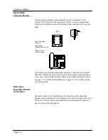
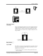
Страница 38: ...ter station and an external ringer in the case of the standard station Refer to the Music On Hold section on page 3 15 and the External Ringer on page 3 17 for further details on these options Extending Keystation Power Connection If a mains outlet is not available near the keystation the maximum distance from a keystation to the mains power can be increased by up to 20 metres This is achieved by ...

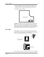
Страница 39: ... metres to connect the keystation to the socket which also allows the connection of two emergency telephones in case of power failure Music On Hold Internal MOH If the PSTN system requires internal MOH the Internal Music On Hold board must be installed on the PSTN Master station PBA The board installation is as shown below Unscrew the two screws on the base of the keystation and remove the base mo...

Страница 40: ...e system then a second internal MOH board must be installed into the second master station This will provide internal MOH to the lines connected to the second master station External MOH External MOH is connected to the master station through the master station s system bus terminal socket External MOH must be connected through an Austel approved Line Isolation Unit LIU The external music connecte...

Страница 41: ...on s system bus terminal socket The standard station external ringer interface provides a 5V 3 mA output Wall Mounting Key Stations Standard keystations can be wall mounted using the Wall Mounting Kit WMK i and a six conductor wall mounting plate Master keystations can be wall mounted in a similar manner to the standard keystation but will require the exchange line cord to be run out from the top ...

Страница 42: ...o the handset retaining clip Fit the keystation to the wall mounting bracket Connect the system bus cable to the keystation and pass it through the wall mount bracket window as shown Connect the external line cable to the master keystation and run the cable out from the top of the station and connect to the external line terminal socket master stations only Option Connection Terminals Master Stati...

Страница 43: ... has not been formally released by Telstra at the time of publication Each Commander i keystation Master or Standard can be connected with a Battery Backup Unit BBU to keep the station functioning normally for up to two hours in the event of mains power failure To ensure that the system operates during a power failure then master station number 1 must be equipped with a BBU If a second master stat...

Страница 44: ...ealed lead acid battery voltage 6V and capacity 1 2 Ah The battery is shipped fully charged 2 Circuitry for battery charging and discharge control the battery lasts for about two hours in normal operation and takes about 13 hours to fully re charge 3 One 2AG style fuse F1 of 0 5A 250V to protect the battery output 4 One jumper link CN3 to disconnect the battery during transport and storage 2 3 Bat...

Страница 45: ...iver used to push the latch on the front side see figure releasing the upper shell to rotate to vertical position When wall mounting the BBU ensure that there is enough space left under the unit to allow insertion of a tool to open the case F1 0 5A L1 Battery 6V 1 2Ah CN1 CN2 To Station From Wall Socket 1 2 3 CN3 CN3 1 2 Battery Connected Operational condition 2 3 Battery Disconnected Factory sett...

Страница 46: ... operation Continue with steps 3 and 4 to begin charging the battery 2 Connect the cable of the BBU to the station if the battery is charged then the station will power up 3 Connect the bus cable coming from the wall socket to CN1 the LED should light steadily green 4 The BBU is now correctly installed Analogue Facilities Unit AFU Wall Installation of AFU Install the AFU near the mains outlet The ...

Страница 47: ...chargers Connection of AFU Plugpack Close the cover this is most important Insert the power cord of the AFU plugpack supplied with a four pin plug into the power connector socket on the front left hand side of the AFU IMPORTANT NOTE When connecting the AFU plugpack to the mains you have five seconds to start up the initial configuration or to re start a new configuration Refer to System initialisa...

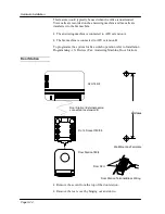
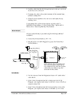
Страница 48: ...ax machine is connected to AFU extension B To programme the system for Fax switch operation refer to Installation Programming 13i Devices Fax Answering Machine Door Station Door Station Remove the screw from the top of the door station Remove the rear cover by hinging out and down Door Station External paging connected to extension B AFU 749 8 RJ 12 Socket 749 38 Door Station 749 4 90 0 mm From AF...

Страница 49: ...r the Telstra Door Unlock Interface Installation Cut the connector from the Plugpack and remove 25 mm from the outer sheath Strip 10 mm of insulation from the red and green wires of the Plugpack join together and connect to the red wire of the Door unlock Interface Unit Strip 10 mm of insulation from the brown and yellow wires of the Plugpack join together and connect to the black wire of the Red ...

Страница 50: ...d stays on for the duration specified in system programming The output between contacts 2 3 is short for the duration specified in system programming The output between contacts 1 3 is open for the duration specified in system programming To programme the length of time the door unlock opens refer to Installation Programming 15i Timer Door Opener External Paging Note The external paging interface ...

Страница 51: ...rminal block polarity is unimportant Terminate the cable to the external paging system to the inner terminals of the terminal block polarity is unimportant Make a test external paging call and adjust the output level pot as required Attach the front assembly to the rear cover and replace the top retaining screw To programme the system for external paging operation refer to Installation Programming...

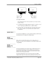
Страница 52: ...emory Clear operation as described in the following pages Press DSS1 and the station will become Master station number 1 If the second Master is needed repeat the four steps above pressing DSS2 to designate Master station number 2 Start connecting the Standard stations one at a time giving each a different identity Do this by pressing the appropriate DSS key WARNING If you allocate the same identi...

Страница 53: ...cs Method 2 By powering up the keystation while pressing the i key To clear the keystation memory Dial 3 to step through the diagnostic menus until the following display is shown Dial 2 to clear the keystation s memory Station Number Clear The station number of any keystation can be cleared from the keystation s diagnostic menu There are two methods of entering diagnostic mode Method 1 From instal...

Страница 54: ...ights steadily for five seconds If after this time it still lights steadily then the AFU has been previously configured 4 Turn off the AFU plug pack to prepare for assigning a number to the AFU The next four instructions steps 5 to 8 must be completed within the initial five seconds after power on 5 Turn on the AFU plug pack 6 Lift the handset of the telephone connected to extension A 7 Dial 8 Rep...

Страница 55: ...m an intercom call between the stations that are the greatest bus distance apart System Programming Once you are sure that all the stations are in working order it is possible to start the system configuration as described in Chapter Four Programming System Programming Back up System programming must be backed up by transferring the data to a second master station if present This will allow the se...

Страница 56: ... locate individual stations or the entire system to a different location without the need for difficult and time consuming re programming or re wiring This is made possible by permanently storing the configuration of the system in the Master station using non volatile memory EEPROM If a user moves to a different office all that is necessary is to unplug the station and take it to the new location ...

Страница 57: ...Chapter Four Programming ...

Страница 58: ...N Programming Default Value 0000 INSTALLATION Programming Default Value 6990 The installation password can be used to also access the administration programming If the USER password is forgotten you can reset it to the factory default value by carrying out the appropriate Administration Programming procedure 07a User Password Reset You can then dial a new user password via User Programming 05u Pas...

Страница 59: ...pectively RECALL Used to insert Hookflash in repertory numbers REDIAL Used to insert Pause in repertory numbers Memory Clear The memory of any keystation can be cleared from the keystation s diagnostic menu If you reset the memory on master station 1 all system programming will be reset to the factory default values If you reset the memory on standard keystations then the standard keystation s per...

Страница 60: ... numbers followed by twenty system speed dial numbers The Default setting is Clear Press i The number stored in location 01 is displayed Use the and keys to scroll backwards and forwards in the display of the 30 stored numbers Alternatively you can go directly to a specific location by dialling the two digit address 01 to 30 Press RLS twice to exit the configuration mode 02 Lock Enable Disable A k...

Страница 61: ...esired location 01 10 by dialling the number or by using the and keys to scroll backwards and forwards Press i to display the Prompt Dial the number to be stored and confirm by pressing i A pause can be stored by pressing REDIAL A hookflash can be stored by pressing RECALL 02u One Touch Speed Dial Numbers Every DSS key except your own and any unused line key can be programmed to store a One Touch ...

Страница 62: ...isplay the prompt Dial the four digit current user password Dial the new password and confirm by pressing i Press RLS to exit from the User main menu 06u Call Waiting Enable Disable Press i twice to enable if disabled or disable if enabled the Call Waiting setting The Default setting is Enable Note It is not recommended to disable call waiting when single line telephones are used as AFU extensions...

Страница 63: ...the sub menus use the and keys Alternatively dial the sub menu number 01a Set Time The Default setting is Clear Press i to display the prompt Dial the time in twenty four hour format using four digits two for the hour followed by two for the minutes Press i to confirm the new time 02a System Speed Dial The Default setting is Clear A maximum of twenty system speed dial telephone numbers may be stor...

Страница 64: ... Press i to display the prompt Dial the appropriate settings for the twelve stations for the selected line number You must enter a value for all twelve even though there may be fewer stations connected to the system Press i to confirm the new setting Note The system must be in night mode to programme the night mode settings 04a Station Call Barring Class Day Night Every station is assigned a call ...

Страница 65: ...ult setting is 123456789 0 Stations 1 to 8 are assigned to DSS1 to DSS8 and stations 9 0 and have intercom call numbers of 9 0 and respectively Note the intercom call number is determined by this programming Press i to display the prompt Dial the DSS and Intercom Call Number allocations in station number sequence You must enter all twelve DSS identifiers 1 even though there may be fewer than twelv...

Страница 66: ...s i to initiate the sending of the data Note Only Master stations of the same software version number should perform this operation otherwise corrupted programming data may occur The software version of the station can be checked from the diagnostic menu 19i 07a User Password Reset The user password for a particular keystation can be reset to the default value The Default setting is Not Applicable...

Страница 67: ...rding to the following options 1 Immediate Ring 2 Delayed Ring 10 seconds 3 Ring Excluded Press i to confirm the Ring Mode WARNING Be careful to avoid ring disabling or delaying for all stations for the same line Note The system must be in night mode to programme the night mode settings 10a Remote Report This facility displays the date and time of the last remote maintenance session In addition th...

Страница 68: ... call is on common hold or exclusive hold before the call rings back at the holding station is programmable There can be different hold reminder times for day and night modes of operation There are four possible settings Press i to display the prompt Dial 1 2 3 or 4 to select the hold reminder time 1 30 seconds 2 60 second 3 90 seconds 4 120 seconds Press i to confirm The Default setting for hold ...

Страница 69: ...t include any standard tone telephone devices connected to AFUs The Default setting is 8 To Change the Number of Stations Press i to display the prompt Dial the number of stations assigned to DSS keys Press i to confirm If the number dialled is less than 8 all icons for any unassigned DSS Keys are deactivated Conversely if the number of assigned stations dialled is greater than the number of stati...

Страница 70: ...efore important as each external line reduces the number of simultaneous intercom conversations 04i Barred ISD Prefixes Ten ISD and high charge information prefixes can be stored on the system Any station that is assigned a Call Barring Class of 1 2 or 3 will be barred from calling these prefixes note that Call Barring Class 4 only permits calls to be made to common allowed prefixes Note Station c...

Страница 71: ...sing the and keys to scroll backwards and forwards Press i to display the prompt Dial the appropriate STD prefix for the selected location Each prefix can be up to four digits Press i to confirm the setting 06i Mobiles Prefixes Ten Mobiles prefixes can be stored on the system These prefixes are to be considered as barring prefixes for stations with a Call Barring Class 3 but allowed prefixes for s...

Страница 72: ...first stored Common Allowed prefix Select the desired Common Allowed prefix location 01 08 by dialling the number or by using the and keys to scroll backwards and forwards Press i to display the prompt Dial the appropriate Common Allowed prefix for the selected location Each prefix can be up to four digits Press i to confirm the setting Note Already included in this table are the prefixes 000 and ...

Страница 73: ...o confirm the setting 09i PABX Access Digit Two single digit PABX access codes can be assigned The Default setting for both locations is 0 Press i to display the first of two PABX access digits Select the desired access digit location 01 or 02 by dialling the number or by using the and keys to scroll backwards and forwards Press i to display the prompt Dial the appropriate digit any dial key digit...

Страница 74: ...ub menu is used to change the installation password The Default setting is 6990 Press i to display the prompt Dial the new four digit installation password Press i to confirm If the installation password is forgotten then the master station 1 will need to be cleared to reset the password back to its factory default setting All other programming will also be reset back to its factory default settin...

Страница 75: ... operation and the AFU ports used for connection of the Door Station External Paging Interface The existing assignments where appropriate are displayed Note The fax switch option requires the i AFU which has not been formally released by Telstra at the time of publication The Default setting is Not Applicable Press i to display the prompt Dial up to three characters as per the following table Pres...

Страница 76: ... connected to extension B of the AFU Door station External paging interfaces must be connected to extension B of the AFU Example 1 To set up a fax switch on AFU 1 only available on i AFU and a door station on AFU 2 then the following is programmed F A D Dialled 9 Displayed 9 Example 2 To set up only a door station external paging interface on AFU 1 then the following is programmed F A D Dialled 6 ...

Страница 77: ...mmand has been given The display shows the current time interval in seconds two digits but the value is normally set to four or five seconds The Default setting is 05 Press i to display the prompt Dial the desired time interval in seconds you must enter two digits Press i to confirm The latest setting will be displayed 16i Type Door Opener This setting is used to select the type of door unlock ope...

Страница 78: ...r terminals in the system from 9 through to 0 Voice terminal 1 Non voice terminal Press i to confirm The latest setting will be displayed 18i AFU Software Version The display shows the current version of the AFU software The Default setting is Not Applicable 19i Keystation Diagnostics Diagnostics can be run on any keystation During the test sequence the keystation is isolated from the system bus E...

Страница 79: ...e voice level is indicated by the number of squares shown on the display Dial 2 to test the Handsfree microphone As above the voice level is indicated by the number of squares shown on the display Press i to return to the original display Dial 3 to go to the next diagnostic menu or press RLS to exit from the Diagnostic Test Sequence To Test Speaker and Music On Hold Dial 1 to test the Speaker with...

Страница 80: ... Test Sequence To Clear the Station Number and Reset Non Volatile Memory Dial 1 to clear the station number The new station number will be requested when you exit the test phase Dial 2 to reset the internal non volatile memory EEPROM and recover the default configuration For a standard station only the personal speed dial numbers will be cleared Dial 3 to go to the next menu or press RLS to exit f...

Страница 81: ...e used for calling into the system Press i to confirm the number 06 Night Status Enable Disable The Night Status allows one system to have a different set of call distribution and station configuration for night time operation It is generally used for after hours operation or whenever the office is not staffed The current setting is displayed The Default setting is Night Disable or Day mode Press ...

Страница 82: ...s 0 Barring Class 1 4 05a DSS Assign the station number 9 0 to the DSS keys or to other intercom numbers 09a Ring Mode Day Night Immediate Ring Delayed Ring 10 seconds Ring Excluded Installation Menu 02i Number of AFU ports Sets the number of AFU ports 2 per AFU 12i Door Station Day Night Enable or Disable incoming calls from the Door Station 13i Devices Assign the AFU ports for fax answering mach...

Страница 83: ......

Страница 84: ...Chapter Five Commander Customer Training ...

Страница 85: ...mers Customers were willing to pay for any additional training required after that The launch of the Commander NT in 1996 saw the Technicians conducting basic user and system administrator training to both Commercial and Corporate customers Because of the Commander i simplicity this was expanded to cover all aspects of customer training on the Commander i keysystem and peripheral equipment Strateg...

Страница 86: ...g Approx 45 min Using the System Administration Manual guide the system administrator through programming Give as much hands on training as possible Approx 20 mins Using the System Administration Manual guide the system administrator through programming Give as much hands on training as possible Train the System Admin to train end users Approx 20 minutes Use the keystation feature card and user ca...

Страница 87: ...ssword Enter into the ADMIN program show the programming categories available how to change time settings show example of setting up speed dial how to initiate station call baring class of service Exchange line ring assignments night service activation deactivation Note Give the system administrator as much hands on as is possible in the given time window Also allow time for questions regarding pr...

Страница 88: ...ls put a call on Hold and Transfer calls Encourage them to go to their System Administrator for other details The end user familiarisation can be done in groups of up to 5 Optional Depends on the installation required Hand out the Commander i Support Centre card and ensure the System Administrator understands fault reporting and inquiry process with the Telstra Commander Remote Access Centre Ensur...

Страница 89: ...Chapter Six Maintenance and Troubleshooting ...

Страница 90: ...us cord bus wiring and termination Check that the master station is connected to the bus and is operating Station shows incorrect characters on the display eg II QQ instead of HH MM Incorrect resistor termination on station or bus wiring incorrect Check the station s resistor termination Check the system bus cabling meets the wiring rules After assigning a station number on a standard station stat...

Страница 91: ...ation Exchange Lines Symptom Likely Causes Busy tone when a line is selected Line icon flashes once and then clears Line not connected Check the 8 wire line cords and exchange line wiring Check that lines 1 and 2 are connected to master station number 1 Check that lines 3 and 4 are connected to master station number 2 Busy tone when a line is selected No handset icon displayed Line not programmed ...

Страница 92: ...tall menu 02i No AFU ports is less than actual number of ports wired For example Number of AFU ports is set to 2 while 2 AFUs are connected should be set to 4 ports Check the system programming 02i No AFU ports Master Station Replacement MOH Card If the master station is to be replaced then ensure that any music on hold daughter boards installed in the master stations are removed and then re inser...

Страница 93: ......

Страница 94: ...Appendix A Installation Summary ...

Страница 95: ...r stations standard stations would then blink their station number for example Basic 4 If the same station number is used for two stations then perform a Number Clear and assign the correct number Once stations are properly initialised customise the system as per user needs Check that exchange lines can be selected AFU connection In Install menu set number of ports 2 for one AFU 4 for two AFUs Con...

Страница 96: ...ersion then use the Send Data function refer Chapter Four System Programming That is Commander i to Commander i phase 1 to phase 1 or Commander i to Commander i phase 2 to phase 2 Note Only Master stations of the same software version number should perform the Send Data operation otherwise corrupted programming data may occur If the system has different versions of master stations then observe the...

Страница 97: ...Max number of units per branch Max number of units within 10 metres of star Maximum bus length 200 metres Terminations 100 ohms at ends of the bus only 2 terminations only No more than four keystations AFUs within any 15 metre segment of cable Master stations can be anywhere on the bus Master station number 1 located within 10 metres of star centre 200 ohms on the end of every branch longer than 1...

Страница 98: ...4 5 6 7 8 9 0 1 2 3 4 5 6 7 8 9 0 2 2 2 2 2 2 2 2 2 2 2 2 2 2 2 2 2 2 2 2 2 2 2 2 1 2 3 4 0 Fully restricted 1 Semi restricted incoming calls only 2 Unrestricted 04a Station Call Barring Class Day Night Station Number Station Number 1 2 3 4 5 6 7 8 9 0 1 2 3 4 5 6 7 8 9 0 0 0 0 0 0 0 0 0 0 0 0 0 0 0 0 0 0 0 0 0 0 0 0 0 0 No Barring 1 Barred ISD 2 Barred ISD STD 3 Barred ISD STD mobiles 4 Common Al...

Страница 99: ...6 7 8 9 0 09a PSTN Ring mode Day Night Line Station Number Station Number 1 2 3 4 5 6 7 8 9 0 1 2 3 4 5 6 7 8 9 0 1 1 1 1 1 1 1 1 1 1 1 1 1 1 1 1 1 1 1 1 1 1 1 1 1 2 3 4 1 Immediate Ring 2 Delayed Ring 3 No Ring 12a Hold Reminder Time 2 1 30 seconds 3 90 seconds 2 60 seconds 4 120 seconds Default values are shown in brackets ...

Страница 100: ...le Prefixes 07i Common Allowed Prefixes 1 001 1 0 1 041 1 1800 2 14 2 2 018 2 013 3 19 3 3 019 3 13 4 0101 4 4 015 4 016 5 0055 5 5 014 5 1100 6 009 6 6 017 6 7 7 7 7 8 12 8 8 8 9 9 9 10 10 10 08i PSTN Line Settings Line Dial Mode Connection Balance Imp Gain Setting Parallel Stn Hook Flash 1 0 1 1 0 0 1 2 3 4 0 Pulse 0 Direct 0 Long 0 High 0 No detect 0 110 ms 1 Tone 1 PABX 1 Short 1 Low 1 Yes det...

Страница 101: ... 9 0 1 1 1 1 1 1 1 1 1 1 1 1 1 1 1 1 1 1 1 1 1 1 1 1 0 Ring Disabled 1 Ring Enabled 0 Ring Disabled 1 Ring Enabled 13i Devices Fax Answering M C Door 14i Interdigit Timeout 15i Timer Door Opener 16i Type Door Opener F A D 10 5 0 AFU 1 AFU 2 9 AFU 1 0 AFU 2 AFU 1 AFU 2 Enter the timeout in seconds Enter the time in seconds 0 Commander i 1 Do not use 17i Data Connection 20i Help Desk ID AFU Stn Sett...

Страница 102: ...Appendix B Factory Default Values ...

Страница 103: ...Dial max 10 Clear 02u User Programmable Key Clear no one touch speed dial numbers 03u Headset Enable Disable Disable 04u Paging Enable Disable Enable 06u Call Waiting Enable Disable Enable 06 Night Status Enable Disable Disable Administration Programming 04 Item No Item Name Default Value 01a System Time Clear 02a System Speed Dial max 20 Clear 03a Line Access Day Night 222222222222 No line access...

Страница 104: ...Item Name Default Value 01i Number of Stations 8 02i Number of AFU Ports 4 03i Number of External PSTN Lines 2 04i Barred ISD Prefixes 001 14 19 0101 0055 009 12 05i Barred STD Prefixes 0 06i Mobiles Prefix Table 041 018 019 015 014 017 07i Common Allowed Prefixes 1800 013 13 016 1100 08i PSTN Line Settings 101100 Tone dial mode connect to exchange short line balance impedance low gain no detectio...

Страница 105: ...nterdigit Time out 010 seconds 15i Timer Door Opener 05 seconds 16i Type Door Station 0 Commander type 1 not used in Australia 17i Data Connection 0000 Voice connection 18i AFU Software Version Not applicable 19i Keystation Diagnostics Not applicable 20i Help Desk ID Clear ...

Страница 106: ...Installation Summary Commander i Product Service Manual Issue 2 Page A 5 Appendix C Commander i Serial Item Numbers ...

Страница 107: ...9 00019 Wall Mounting Kit Commander i WMK i 3AU 30075 AAAA AA 749 00020 Plug Pack Socket Commander i PPS i 8CF 00058 7162 YY 749 00021 Battery Station Backup Commander i BBU i 8CF 00058 7163 YY 749 00022 Directory Card Commander i DC i 8CF 00058 7164 YY 749 00023 Card DSS Commander i DOC i DSS 8CF 00058 7165 YY 749 00024 Manual Station QRC Commander i DOC i QRC 8CF 00058 7166 YY 749 00025 Manual S...

Страница 108: ...art No 749 00041 DSS Panel Commander i 8CF 00058 7297 YY 749 00042 Station Master Commander i TS i412 M 8CF 00058 7325 YY 749 00043 Station Standard Commander i TS i412 S 8CF 00058 7326 YY 749 00046 Hookswitch Springs 3AU 30069 ABAA AA ...

Страница 109: ...Appendix D Commander i System User Guide ...

Страница 110: ...Telstra Commander i System User Guide Serial Item 749 025 Issue 2 ...

Страница 111: ...ems with the documentation for this Commander i product please tell us We want to know if you find any of the following problems mistakes in the manual any part is hard to understand difficulty in locating a subject format hard to follow etc The staff at Telstra Commander Remote Access Centre are keen to assist However please read carefully the documentation provided with the product before callin...

Страница 112: ...lls 4 6 5 Other Facilities 5 1 Message Wait 5 2 PSTN Decadic to Tone Signalling 5 3 Do Not Disturb DND 5 3 Microphone Mute 5 4 Monitor 5 4 Remote Maintenance 5 5 6 Programming 6 1 Menus 6 2 01 Repertory 6 2 02 Keystation Locking 6 3 06 Night Status Enable Disable 6 4 03 User Programming 6 5 01u Personal Speed Dial Numbers 6 5 02u One Touch Speed Dial Numbers 6 6 03u Headset Enable Disable 6 7 04u ...

Страница 113: ...1 Getting To Know Your Commander i ...

Страница 114: ...ercom Automatic Answer HF GL Key To activate handsfree speaker and group listening facilities INT Key To make an intercom call ICON Display This provides a display of system activities as well as the status of the keystation For more information refer to Visual Signals on page 1 6 RLS Release Key a To release an active call whilst in handsfree mode of operation b To exit programming mode c To rele...

Страница 115: ...0 All calls permitted Class 1 Calls to ISD and info call prefixes barred Calls to STD mobile and common allowed prefixes permitted Class 2 Calls to ISD STD and info call prefixes barred Calls to specified mobile and common allowed prefixes permitted Class 3 Calls to ISD STD mobile and info call prefixes barred Local calls and calls to specified common allowed prefixes permitted Class 4 Only calls ...

Страница 116: ...ns the meaning of each symbol L1 L2 L3 L4 RECALL HO LD DN D REDI AL VO L M UTE AA 1 2 3 4 5 6 7 8 I N T HF G L own st at i on of f hook st at i on i n heads etm ode m essage wai t f r om St n 3 St n 5 on DN D St n 6 unpl ugged t hi sst n t al ki ng t o St n 8 i ncom i ng i nt er com cal l handsf r ee act i vat ed l i ne 1 engaged on anot herst at i on i ncom i ng cal l on l i ne 2 l i ne 3 on excl...

Страница 117: ...2 Answering Calls ...

Страница 118: ...matically answers and two way speech is established in handsfree mode One beep is heard from the speaker before the speech path is connected Internal Paging Calls Announcements can be made through the speakers of idle keystations pre programmed to receive paging calls To Answer A Paging Call Hear the paging call through keystation speaker Lift the handset or to answer in handsfree press HF GL INT ...

Страница 119: ...ring mode setting does not affect the ability of a station to answer an incoming call For more information on the ring mode settings refer to Administration Programming 09a Ring Mode PSTN on page 6 18 System Call Waiting Call Waiting is available on the system for both internal and external calls A short tone burst is heard every twenty seconds if you are already busy on a call and another incomin...

Страница 120: ...3 Making Calls ...

Страница 121: ...station 3 L2 L3 1 2 3 4 L1 If the called keystation is in automatic answer mode a long beep is heard instead of the ring tone and the call is automatically answered in handsfree mode at the called keystation For systems with more than eight extensions intercom calls made to stations 9 10 11 and 12 must be made by pressing INT and dialling 9 0 and respectively Paging Calls To Make An Internal Pagin...

Страница 122: ...y system speed dial numbers 11 30 For speed dial number storing procedures refer to User Programming 01u Personal Speed Dial Numbers on page 6 5 and Administration Programming 02a System Speed Dial Numbers on page 6 11 To Dial a Stored Number Lift the handset if handset mode is desired Press a free LINE and wait for dial tone Press i and dial the speed dial address number 01 30 or Scroll up and do...

Страница 123: ...4 Call Handling ...

Страница 124: ...ld timer refer to Administration Programming 12a Hold Timer on page 6 20 The standard Music On Hold is a non musical tone Thirty two seconds of digitised music is available as an option as is external Music On Hold L2 L3 1 2 3 4 L1 To Place An External Call On Exclusive Hold Ask the external party to wait Press HOLD twice L2 L3 1 2 3 4 L1 Replace the handset Call retrieval is the same as for calls...

Страница 125: ...e hold L2 L3 1 2 3 4 L1 Transfer Without Announcement Camp On Hang up before the called party answers or upon hearing busy ring tone L2 L3 1 2 3 4 L1 At the transferred keystation the call is presented as an incoming call and the display indicates which station is transferring the call L2 L3 1 2 3 4 L1 If the called station does not answer the transferred call within the pre programmed time the ca...

Страница 126: ...n DSS key with the flashing middle bar icon to start the conference L2 L3 1 2 3 4 L1 To Set Up A Conference Call With Two External Parties Ask external party to wait Press a free LINE Make call to second external party Inform the new party about impending conference L2 L3 1 2 3 4 L1 Press own DSS key with the flashing middle bar icon to start the conference L2 L3 1 2 3 4 L1 I1 Conference Conferenc...

Страница 127: ...5 Other Facilities ...

Страница 128: ...d DSS2 in the above diagram Speak when the called party answers PSTN Decadic to Tone Signalling To Activate Tone Signalling On A PSTN Decadic Line Press a free LINE Press Dial the desired number To Resume Decadic Dialling Press RECALL Do Not Disturb DND This facility allows you to block audible signalling on your keystation You can still answer external calls as normal by lifting the handset and p...

Страница 129: ...t your premises For security reasons this feature can only be activated by the system administrator Warning this feature should not be used except under the directions of a Telstra representative Before using this feature call the Telstra Commander Remote Access Centre Remote maintenance takes place on Line 1 Ensure that Line 1 is available and the first master keystation in your system is idle If...

Страница 130: ...word is incorrect the keystation will return to the Telstra Commander Remote Access Centre call Press i 9 9 and re enter the correct password Wait for dial tone Enter the phone number given to you by the Telstra representative Wait for the Remote Maintenance System to answer the call and say Welcome to the Telstra Commander Remote Access Centre L2 L3 1 2 3 4 L1 Press the DSS key of the first maste...

Страница 131: ...6 Programming ...

Страница 132: ...play Stored Speed Dial Numbers Press i to enter programming mode Press i to display the first number Dial the required two digit address 01 to 30 Alternatively scroll up or down the list of numbers using the and keys Press RLS twice to exit 02 Keystation Locking A keystation can be prevented from making all external calls other than those numbers in the allowed numbers list or system speed dial nu...

Страница 133: ...eystation can be programmed with a maximum of ten personal speed dial numbers and up to ten one touch speed dial keys These are in addition to the twenty system speed dial numbers and can only be used at the keystation where the numbers are stored To Store Personal Speed Dial Numbers Press i to enter programming mode Dial 03 to go to the User menu Press i to confirm Press i again The first persona...

Страница 134: ...es to exit Note Locations 01 to 08 correspond to DSS1 to DSS8 Locations 09 to 11 correspond to L2 L3 and L4 if unused 03u Headset Enable Disable A keystation handset may be replaced by a suitable Austel permitted headset When connected and activated the RLS key is used to perform the hookswitch function To Enable Disable Headset Press i to enter programming mode Dial 03 to go to the User menu Pres...

Страница 135: ...to exit 06u Call Waiting Enable Disable A keystation can be programmed so that it does not receive the call waiting tone when a second call external or internal arrives at the keystation To Enable Disable Call Waiting Press i to enter programming mode Dial 03 to go to the User menu Press i to confirm Dial 06 to go to the Call Waiting option Press i twice to change the setting Press RLS three times...

Страница 136: ...tion The maximum size for any number is twenty four digits Press REDIAL to store a pause RECALL to store a hookflash To Store System Speed Dial Numbers Press i to enter programming mode Dial 04 to go to the Administration menu Press i to confirm Enter four digit administration password and press i If the password is incorrect the Admin menu is displayed Press i and re enter correct password or pre...

Страница 137: ...opriate setting for the twelve stations You must enter twelve values even though you may not have twelve stations If any of the entered numbers are invalid the original setting for that station will be retained Press i once to confirm twice to re enter or RLS to cancel If desired repeat the above process by selecting another line number and entering the appropriate status codes Press RLS four time...

Страница 138: ... digit administration password and press i If the password is incorrect the Admin menu is displayed Press i and re enter correct password or press RLS to exit Enter 05 to go to the DSS option The position in which each of the DSS keys is displayed indicates which station is connected to it In the example shown below station 3 is connected to DSS6 and station 6 is connected to DSS3 Press i to confi...

Страница 139: ...ation password and press i If the password is incorrect the Admin menu is displayed Press i and re enter correct password or press RLS to exit Enter 07 to go to the User Password Reset option Press i to confirm Enter keystation number to be reset 1 8 Press i to confirm Press RLS three times to exit 08a Administration Password To Set The Administration Password Press i to enter programming mode Dia...

Страница 140: ... any of the entered numbers is invalid the original setting for that station will be retained Press i once to confirm twice to re enter or RLS to cancel Repeat the above steps for the other available line numbers Press RLS four times to exit WARNING Be careful to avoid ring disabling or delaying for all stations for the same line 10a Remote Report This facility displays the date and time of the la...

Страница 141: ... call is on common hold or exclusive hold before the call rings back at the holding station is programmable There are four possible settings 1 30 seconds 2 60 second 3 90 seconds 4 120 seconds To Set The Hold Timer Day Or Night Press i to enter programming mode Dial 04 to go to the Administration menu Press i to confirm Enter four digit Administration password and press i If the password is incorr...

Страница 142: ...Appendix F Commander i AFU User Guide ...

Страница 143: ...Telstra Commander i Analogue Facilities Unit User Guide Serial Item 749 35 Issue 2 ...

Страница 144: ...1800 044 113 Calls from a mobile phone are charged at the applicable mobile rate These numbers are staffed from 8 00 am to 7 00 pm EST from Monday to Friday Table of Contents 1 Introduction 1 1 Introduction 1 2 Main Characteristics 1 2 Main Features 1 2 Audible Signals 1 4 2 How To Use The AFU 2 1 Foreword 2 2 Internal Calls 2 2 To Make an Internal Call 2 2 To Answer an Internal Call 2 2 To Make a...

Страница 145: ...1 Introduction ...

Страница 146: ...lls such as international calls STD calls and calls to mobiles System Speed Dialling To provide a station with the ability to dial the twenty system common speed dial numbers each number made up of a maximum of 24 digits Night Service To be able to activate with a single command a different set of call distribution and station configuration for night time operation eg at the closing time of the of...

Страница 147: ...uide Issue 2 Audible Signals Ring Type Call Type Double ring External call or transferred call reverting Fast single ring Internal call Slowsingle ring Door station call Single tone repeated through handset Call waiting Page 1 5 Page 1 4 ...

Страница 148: ...2 How To Use The AFU ...

Страница 149: ...es connected to the caller in the same way as an internal call All keystations programmed to receive paging calls are alerted with a double beep on the loudspeaker and also a message on the display External Calls To Make an External Call Lift the handset and listen for internal dial tone Dial 0 to access a direct external line or 8 to access a PABX line When you hear the external dial tone dial th...

Страница 150: ...cally restored If the called station does not answer the transferred call within the pre programmed time the call will revert back to your phone Speed Dialling You can dial on both direct external and PABX lines a repertory number stored in the System Speed Dial numbered from 11 to 30 Note System Speed Dial is not subject to Station Class Of Service Barring To Use System Speed Dialling on an Exter...

Страница 151: ... To change the mode of dialling to the external line from Pulse Decadic to Tone DTMF Press the RECALL or Flash key and wait for the internal dial tone Dial followed by the required number Door Station Door Opener It is possible to answer the door station and operate the door opener if equipped from any station when in conversation with the door station To Operate the Door Opener Call from Door Sta...

Страница 152: ...3 AFU Quick Reference Card ...

Страница 153: ...ne Dial required system speed dial number 11 to 30 To Speed Dial on a PABX Line Lift handset Dial 78 and wait for dial tone Dial required system speed dial number 11 to 30 Holding Calls Ask outside caller to wait Press RECALL key and listen for internal dial tone Dial 1 To Recover A Call on Hold Lift handset and listen for internal dial tone Dial 1 Inquiry Calls Transfers To Make an Inquiry Call A...

Страница 154: ...Installation Summary Commander i Product Service Manual Issue 2 Page A 9 Appendix G Technical Bulletins ...

Страница 155: ...Sales Operations Susan Pearson 08 8202 9648 1 2 3 4 5 6 7 8 9 0 ABC D EF G H I JKL M N O PQ RS TU V W XYZ L1 L2 L3 L4 RECALL H O L D D N D REDI AL VO L M U TE AA 1 2 3 4 5 6 7 8 I N T H F G L i RLS Technical Bulletin BULLETIN No 9 January 1997 No of pages including this one 2 ...

Страница 156: ...as been issued by Sales Development and Training Commander Sales Operations Susan Pearson 08 8202 9648 Series 9 2 January 1997 DOCUMENTS INCLUDED IN THIS BULLETIN DATE EQUIPMENT TOPIC REFERENCE 13 1 97 Commander i Potential Faint Reception i1000 ...

Страница 157: ...i customers experiencing faint reception Programming In the vast majority of cases these difficulties can be overcome by changing programming data The programming area to check is 05 install 08i line settings refer to page 4 12 of System Installation Manual Current default data for each line is 101100 note that this default data has changed since the manuals were printed The 1 in positions 3 4 of ...

Страница 158: ... are unsuccessful Although the programming changes will work in most circumstances there may still be occasions where the faint reception is still a problem In these cases please contact the Telstra Commander Remote Access Centre on 1800 809 881 for further help The Future Work is being done with the manufacturer to assess whether any changes to default data are required at manufacture Later bulle...

Страница 159: ...ander Sales Operations Susan Pearson 08 8202 9648 TELSTRA IN CONFIDENCE 1 2 3 4 5 6 7 8 9 0 ABC D EF G H I JKL M N O PQ RS TU V W XYZ L1 L2 L3 L4 RECALL H O L D D N D REDI AL VO L M U TE AA 1 2 3 4 5 6 7 8 I N T H F G L i RLS Technical Bulletin BULLETIN No 17 March 1997 ...

Страница 160: ...velopment and Training Commander Sales Operations Susan Pearson 08 8202 9648 Series 17 2 February 1997 No of pages including this one 3 DOCUMENTS INCLUDED IN THIS BULLETIN DATE EQUIPMENT TOPIC REFERENCE 3 3 97 Commander i Modification to improve i1001 Receive Level Volume ...

Страница 161: ... distances from the local exchange As the Commander i408 does not as yet have variable receive volume control a modification to internal Handset acoustics has been designed which provides a significant increase to the handset receive level This modification will be incorporated in all future stock commencing from March It should be noted that less than 10 of installations have experienced this dif...

Страница 162: ...is default data has changed since the manuals were printed Remember to change the setting for each line The 1 in positions 3 4 of this string represent Balance Impedance 1 Short Line Gain Setting 1 Low PABX By changing one or both of these settings to 0 for Long Line and or 0 for High C O most customers report the new levels are acceptable The default will be changed to 100000 once new stock arriv...

Страница 163: ... or if requested a technician may be despatched to do this Any existing customer who is experiencing difficulties who is not on the current TCRAC database will not receive this modification This modification is not available to existing customers via any other process Therefore please ensure that the above process is followed Future Product Enhancements It is expected that this latest modification...

Страница 164: ...nder Sales Operations Susan Pearson 08 8202 9648 TELSTRA IN CONFIDENCE 1 2 3 4 5 6 7 8 9 0 ABC D EF G H I JKL M N O PQ RS TU V W XYZ L1 L2 L3 L4 RECALL H O L D D N D REDI AL VO L M U TE AA 1 2 3 4 5 6 7 8 I N T H F G L i RLS Commander i Technical Bulletin BULLETIN No 27 ...

Страница 165: ...ales Development and Training Commander Sales Operations Susan Pearson 08 8202 9648 Series 27 2 May 1997 May 1997 No of pages including this one 2 DOCUMENTS INCLUDED IN THIS BULLETIN DATE EQUIPMENT TOPIC REFERENCE 28 5 97 Commander i Station Based Amplifiers i1003 ...

Страница 166: ...the Station Based Amplifier of the type that is supplied as 727 34 To ensure correct operation of the Station Based Amplifier the Commander i station needs to be of PCS01 issue If the Station Based Amplifier is required at an existing station of PCS02 issue a station of PCS01 will need to be sourced to replace the existing station Station issue is printed on the label glued to the underside of eac...

Страница 167: ...Technical Bulletin Ref i1003 This bulletin has been issued by Sales Development and Training Commander Sales Operations Susan Pearson 08 8202 9648 Series 27 4 May 1997 1800 809 881 ...

Страница 168: ...nder Sales Operations Susan Pearson 08 8202 9648 TELSTRA IN CONFIDENCE 1 2 3 4 5 6 7 8 9 0 ABC D EF G H I JKL M N O PQ RS TU V W XYZ L1 L2 L3 L4 RECALL H O L D D N D REDI AL VO L M U TE AA 1 2 3 4 5 6 7 8 I N T H F G L i RLS Commander i Technical Bulletin BULLETIN No 35 ...

Страница 169: ... Development and Training Commander Sales Operations Susan Pearson 08 8202 9648 Series 35 2 June 1997 June 1997 No of pages including this one 2 DOCUMENTS INCLUDED IN THIS BULLETIN DATE EQUIPMENT TOPIC REFERENCE 11 6 97 Commander i Maintenance Serial i1004 Item Update ...

Страница 170: ...ond digitally recorded Music On Hold Card 749 15 CORD LINE _ MASTER KEYSTATION Line Cord from Terminal socket to Master Keystation 749 16 CORD BUS _ KEYSTATION AFU Bus Cord from Terminal socket to Keystation AFU 749 17 CORD HANDSET _ COMMANDER i Cord only from station to Handset 749 18 HANDSET _ COMMANDER i Handset only 749 22 DIRECTORY CARD _ COMMANDER i System Keystation Abbreviated Number Direc...

Страница 171: ...DER i Bus Socket for Keystation AFU 749 39 TERMINAL BLOCK _ LINE COMMANDER i Line Socket for Master Keystation 749 40 ADAPTOR _ AC AFU COMMANDER i Analogue Feature Unit Power Supply Plug Pack 749 41 PANEL _ DSS COMMANDER i Station DSS panel plastic cover These parts are available via the normal parts ordering process For further information please contact the Telstra Commander Remote Access Centre...

Страница 172: ...tions Susan Pearson 08 8202 9648 STRICTLY FOR TELSTRA STAFF ONLY TELSTRA IN CONFIDENCE 1 2 3 4 5 6 7 8 9 0 ABC D EF G H I JKL M N O PQ RS TU V W XYZ L1 L2 L3 L4 RECALL H O L D D N D REDI AL VO L M U TE AA 1 2 3 4 5 6 7 8 I N T H F G L i RLS Commander i Technical Bulletin BULLETIN No 57 ...

Страница 173: ...Training Commander Sales Operations Susan Pearson 08 8202 9648 Bulletin 57 2 January 1998 STRICTLY FOR TELSTRA STAFF ONLY February 1998 No of pages including this one 2 DOCUMENTS INCLUDED IN THIS BULLETIN DATE EQUIPMENT TOPIC REFERENCE 4 12 98 Commander i Phase 1 Switch hook i1007 Spring Replacement 749 46 ...

Страница 174: ...ement of the switch hook then contact on the circuit board is not made if the line key is pressed in this state a call will go into handsfree automatically because the System will recognise the Switch hook as Onhook hung up The Phase 2 Stations have an improved compression spring that can be fitted to the Phase 1 Stations Master Standard The spring is now available in packs of 20 with the Serial a...

Страница 175: ...front of the station 5 Press the two sides of the switch hook mechanism inwards to remove from the two raised pivot posts on the station case 6 Replace the Phase 1 compression spring with the new Phase 2 compression spring 749 46 7 Reassemble the station using steps 3 to 5 in reverse order being careful to replace all of the 15 screws into the correct position 8 Once the station is assembled to th...

Страница 176: ...tions Susan Pearson 08 8202 9648 STRICTLY FOR TELSTRA STAFF ONLY TELSTRA IN CONFIDENCE 1 2 3 4 5 6 7 8 9 0 ABC D EF G H I JKL M N O PQ RS TU V W XYZ L1 L2 L3 L4 RECALL H O L D D N D REDI AL VO L M U TE AA 1 2 3 4 5 6 7 8 I N T H F G L i RLS Commander i Technical Bulletin BULLETIN No 59 ...

Страница 177: ...nd Training Commander Sales Operations Susan Pearson 08 8202 9648 Bulletin 59 2 January 1998 STRICTLY FOR TELSTRA STAFF USE ONLY January 1998 No of pages including this one 3 DOCUMENTS INCLUDED IN THIS BULLETIN DATE EQUIPMENT TOPIC REFERENCE 29 1 98 Commander i Reinstallation of i1008 Music on Hold cards ...

Страница 178: ...ng reinstalled into the replacement Master station This is causing customer dissatisfaction and additional rework and cost when replacing a Master station we MUST check for the presence of the Music on Hold card using the process below and reinstall in the new Master station The Internal Music on Hold can be tested in 19i Station Diagnostics follow the steps on page 4 16 4 17 of your Installation ...

Страница 179: ...d is a small daughter board directly below the switch hook See diagram on next page 5 If installed remove the card for reinstallation in the replacement Master station once the card has been removed or if the card was not installed reassemble the station 6 Follow the above steps for installing the Music on Hold card in the replacement Master station and programme the System for Internal Music opti...

Страница 180: ...CE This bulletin has been issued by Sales Development and Training Commander Sales Operations Susan Pearson 08 8202 9648 Bulletin 59 5 January 1998 STRICTLY FOR TELSTRA STAFF USE ONLY C L I 4 pin connector 3 pin connector Master Station PBA MOH Board ...

Страница 181: ...in has been issued by Sales Development and Training Commander Sales Operations Susan Pearson 08 8202 9648 Bulletin 59 6 January 1998 STRICTLY FOR TELSTRA STAFF USE ONLY For more information please contact the Telstra Commander Remote Access Centre on 1800 809 881 ...

Страница 182: ...tions Susan Pearson 08 8202 9648 STRICTLY FOR TELSTRA STAFF ONLY TELSTRA IN CONFIDENCE 1 2 3 4 5 6 7 8 9 0 ABC D EF G H I JKL M N O PQ RS TU V W XYZ L1 L2 L3 L4 RECALL H O L D D N D REDI AL VO L M U TE AA 1 2 3 4 5 6 7 8 I N T H F G L i RLS Commander i Technical Bulletin BULLETIN No 60 ...

Страница 183: ... Training Commander Sales Operations Susan Pearson 08 8202 9648 Bulletin 60 2 February 1998 STRICTLY FOR TELSTRA STAFF USE ONLY February 1998 No of pages including this one 3 DOCUMENTS INCLUDED IN THIS BULLETIN DATE EQUIPMENT TOPIC REFERENCE 9 2 98 Commander i Transfer of data i1009 between Master stations ...

Страница 184: ...and Master 2 until completed To Send The Data Press i to enter programming mode Dial 04 to go to the Administration menu Press i to confirm Enter four digit administration password and press i If the password is incorrect the Admin menu is displayed Press i and re enter correct password or press RLS to exit Enter 06 to go to the Send Data option Press i to initiate the sending of the data Note It ...

Страница 185: ...to perform a number clear 19 i Station Diagnostics 1 NumClr and renumber the replacement Master station as DSS 1 you can now reinstall Standard Station 2 and test the System for correct operation If Send Data is to be performed on a System with 2 Master stations then the process is a lot easier Send Data from Master station 1 to Master station 2 then perform a number clear 19 i Station Diagnostics...

Страница 186: ...efault No other User Admin or System Data be lost Note Please check for the presence of MOH cards and reinstall into the replacement Master stn WARNING Transferring of Data is performed in Administration Programming 06a Send Data This must not be performed between unlike Master stations e g Phase1 to Phase2 or Phase2 to Phase 1 Data corruption will occur if this warning is ignored This can also af...

Страница 187: ...tions Susan Pearson 08 8401 7857 STRICTLY FOR TELSTRA STAFF ONLY TELSTRA IN CONFIDENCE 1 2 3 4 5 6 7 8 9 0 ABC D EF G H I JKL M N O PQ RS TU V W XYZ L1 L2 L3 L4 RECALL H O L D D N D REDI AL VO L M U TE AA 1 2 3 4 5 6 7 8 I N T H F G L i RLS Commander i Technical Bulletin BULLETIN No 62 ...

Страница 188: ... Access Centre on 1800 809 881 This bulletin has been issued by Sales Development and Training Commander Sales Operations Susan Pearson 08 8401 7857 Bulletin 62 2 March 1998 March 1998 No of pages including this one 5 DOCUMENTS INCLUDED IN THIS BULLETIN DATE EQUIPMENT TOPIC REFERENCE 2 3 98 Commander i Release i1010 ...

Страница 189: ... extensive retrofit procedure underway to replace all Phase 2 Master stations to address the known problems associated with this version of software See page 4 for retrofit and upgrade procedures Below is a list of all known problems associated with the Phase 2 Master which have all been resolved in this version of software 1 Stations intermittently can display incorrect information in 2 ways Stat...

Страница 190: ... looking in Install and Admin programming it is possible to see incorrect values and corruption of the customer data 3 Station Personal speed dial numbers dialled from standard stations have an additional key press of the i key to dial the speed dial number 4 Station One Touch Speed Dialling numbers cannot store the Recall facility in the digits to be dialled 5 Systems configured with only 2 Keyst...

Страница 191: ...is now an additional procedure that must always be completed when initialising an AFU with a Commander i Master station The AFU power must be switched off for a minimum of 20 Seconds once the AFU Initialisation sequence has been completed then switched back on This additional procedure will be in all future documentation The new full AFU initialisation sequence including the additional procedure a...

Страница 192: ...FIDENCE For more information please contact the Telstra Commander Remote Access Centre on 1800 809 881 This bulletin has been issued by Sales Development and Training Commander Sales Operations Susan Pearson 08 8401 7857 Bulletin 62 6 March 1998 ...

Страница 193: ...leted within the initial five seconds after power on 5 Turn on the AFU plug pack 6 Lift the handset of the standard tone telephone connected to extension port A 7 Dial 8 Replace the handset The above operation clears the AFU memory and the LED starts flashing The AFU is now ready to receive its new identity number 9 Lift the handset of the standard tone telephone connected to extension port A no d...

Страница 194: ...here is now an extensive retrofit procedure underway to replace all Phase 2 Master stations to address the known problems associated with this version of software Telstra and the Manufacturer Alcatel are replacing all Phase 2 stations from the field all customer sites with Phase 2 Installations have been identified using S Plus and these sites will all be replaced as soon as possible at no charge ...

Страница 195: ...ir existing Commander i system need to change their Master Station only Master Station number 1 needs to be changed The cost of this upgrade to Commander i Master Station for both rental and purchased systems is a once only equipment charge of 360 and normal Fee For Service charges for the installation and programming To fully upgrade to a complete Commander i system giving variable volume control...

Отзывы: