2-14
BRC-300/300P
BRU-300/300P
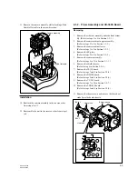
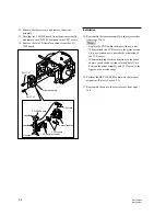
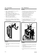
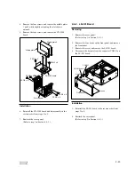
2-2-4. DD-208 Board
Removing
1.
Remove the side rear assembly and side front assem-
bly. (Refer to steps 1 to 3 in Section 1-3-1.)
2.
Remove the camera cabinet upper assembly.
(Refer to steps 2 to 5 in Section 1-3-2.)
3.
Remove the camera cabinet lower.
(Refer to steps 3 to 5 in Section 1-3-3.)
4.
Remove the shield chassis.
(Refer to step 6 in Section 2-2-6.)
5.
Disconnect the flexible flat cable from the connector
CN001 on the DD-208 board.
6.
Remove the two screws, and remove the DD-208
board.
Installation
7.
Reinstall the DD-208 board in the reverse order from
steps 5 and 6.
8.
Perform the BRC-300/300P camera block electrical
alignment. (Refer to Section 3-2.)
9.
Reassemble the unit in the reverse order from steps 1
to 4.
BTP2
x
6
B2
x
3
DD-208 board
CN001
Flexible flat cable
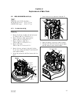
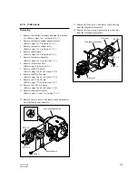
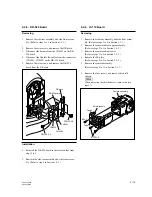
2-2-3. DC-130 Board
Removing
1.
Remove the base plate. (Refer to Section 1-3-4.)
2.
Remove the SY-314 board.
(Refer to steps 2 to 4 in Section 2-2-11.)
3.
Remove the blank panel. (Refer to Section 1-3-5.)
4.
Remove the EXP chassis assembly and CC-91 board.
(Refer to steps 4 to 6 in Section 2-2-1.)
5.
Remove the CN chassis assembly.
(Refer to steps 5 and 6 in Section 2-1-4.)
6.
Remove the screw, and remove the DC-130 board.
7.
Disconnect the harness from the connector CN2451 on
the DC-130 board.
Installation
8.
Reinstall the DC-130 board in the reverse order from
steps 6 and 7.
9.
Reassemble the unit in the reverse order from steps 1
to 5.
DC-130 board
PSW2.6
x
6
CN2451
CN chassis assembly

