3-42
BRC-300/300P
BRU-300/300P
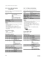
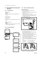
Embedded CRC SMPTE RP165 FF: OK AP: OK
SDI waveform monitor
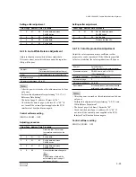
Jitter level
SDI waveform monitor
Measured jitter (P-P)
Timing : (10 Hz)
759.5 ps (0.200 UI)
SDI waveform monitor
A
BRC-300/300P
EX-947
board
S002
ADJ
OPE
S002
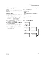
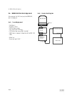
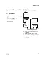
3-6. BRBK-302 Electrical Alignment
5.
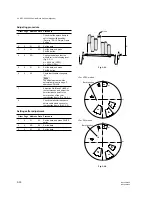
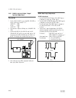
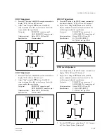
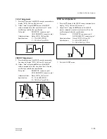
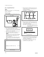
Change the display of the SDI waveform monitor to
the EYE pattern mode, and check that signal level A
satisfies the specification.
Specification:
A = 720
±
80 mV p-p
6.
Change the display of the SDI waveform monitor to
the jitter measurement mode, and check that the jitter
level satisfies the specification.
Specification:
When the high-pass filter is set to 10
Hz and 1 kHz, both the jitter levels are
less than 0.200 UI.
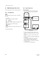
7.
Press the BACK LIGHT button of the SIRCS remote
commander to output a video signal from the SDI
OUT connector of BRBK-302.
8.
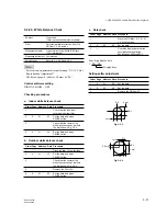
Shoot the pattern box by the BRC-300/300P, and
check that the video signal is normal.
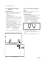
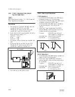
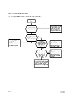
3-6-4. Output Video Check
n
Before this check, perform “3-6-3. VCO Free-running
Frequency Adjustment”.
Check Procedure
1.
Set the switch S002 on the EX-947 board to ADJ.
2.
Turn on the power of the BRC-300/300P.
3.
Press the BACK LIGHT button of the SIRCS remote
commander to output a 75 % color-bar signal from the
SDI OUT connector of BRBK-302.
4.
Check that an error message is not displayed on the
status display of the SDI waveform monitor.
n
When using the SDI waveform monitor WFM700M,
check that the message “SMPTE RP165 FF:OK
AP:OK” is displayed.
When using another SDI waveform monitor, check
that the format matches the format of the BRC-300/
300P.

