4-1
BRC-300/300P
BRU-300/300P
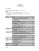
Model
Description
Page
BRC-300/300P
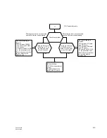
a-1.
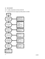
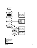
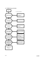
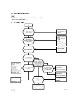
The power indicator does not light and PAN/TILT operations are disabled.
4-2
a-2.
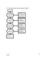
The power indicator lights, but PAN/TILT operations are disabled.
4-3
a-3.
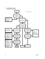
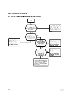
The STANDBY lamp blinks.
4-4
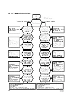
PAN/TILT reset is incorrect.
a-4.
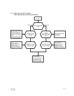
The PAN/TILT motors do not rotate.
4-6
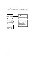
a-5.
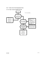
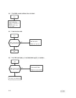
Image remains “blueback” at the end of PAN/TILT operations.
4-7
a-6.
Image is distorted.
4-8
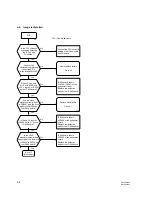
a-7.
Supplied SIRCS remote commander does not function.
4-10
a-8.
External sync does not function.
4-11
Video output becomes out of synchronization.
a-9.
No operation is available with RS-232C/RS-422 interface.
4-12
a-10. No image is output from BRBK-301/302/304.
4-13
a-11. BRBK-303 does not function.
4-14
BRC-300/300P
b-1.
No image is output.
4-15
(Camera Block)
b-2.
The VISCA control software does not start.
4-16
b-3.
Focus is abnormal.
4-16
b-4.
The CCD is defective, or has black/white spots or scratches.
4-16
BRU-300/300P
c-1.
The power indicator does not light and image is not displayed after power-on.
4-17
c-2.
The power indicator blinks in red, and “communication error” appears on the monitor.
4-18
c-3.
The power indicator lights, but no image is output from the VIDEO OUT or S VIDEO OUT
4-19
connector.
c-4.
The power indicator lights, but the video output sync is abnormal.
4-20
c-5.
No operation is available with RS-232C/RS-422 interface.
4-21
c-6.
The power indicator lights, but the optional card does not function.
4-22
RM-BR300
d-1.
The LED does not light after power-on.
4-23
d-2.
Camera operations are not available.
4-24
BRBK-301
e-1.
Image is not displayed.
4-26
e-2.
Image is displayed, but the signal is abnormal.
4-28
Menu operations are not reflected.
e-3.
The RGB output sync is abnormal.
4-29
BRBK-302
f-1.
Image is not displayed.
4-30
BRBK-303
g-1.
Image is not displayed.
4-32
BRBK-304
h-1.
Image is not displayed.
4-34
Section 4
Troubleshooting
4-1. Overview
This section describes countermeasures to be taken if each model becomes defective.
Refer to the following table to identify the defective part.
m
.
If each model becomes defective after installation or repair service, check that the model has been
correctly installed or repaired before referring to the following table.
.
The voltage and frequency values described in this section are reference values. Use them as references
for troubleshooting.

